CONTINUOUSLY VARIABLE TRANSAXLE SYSTEM, Diagnostic DTC:P0712, P0713
| DTC Code | DTC Name |
|---|---|
| P0712 | Transmission Fluid Temperature Sensor "A" Circuit Low Input |
| P0713 | Transmission Fluid Temperature Sensor "A" Circuit High Input |
DESCRIPTION
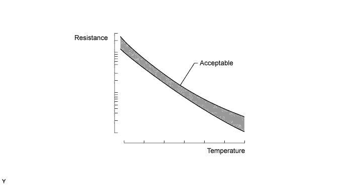
The CVT fluid temperature sensor converts the fluid temperature into a resistance value which is detected by the ECM.
The sensor resistance changes with the CVT fluid temperature. As the temperature rises, the sensor resistance decreases. The ECM applies a voltage to the temperature sensor through ECM terminal THO1 and calculates the fluid temperature based on the voltage signal.
Tech Tips
The CVT fluid temperature is likely to increase under conditions such as towing, climbing hills and in heavy traffic.
| DTC Code | DTC Detection Condition
|
Trouble Area |
|---|---|---|
| P0712 |
|
|
| P0713 |
|
|
MONITOR DESCRIPTION
The CVT fluid temperature sensor converts the CVT fluid temperature to an electrical resistance value. Based on the resistance, the ECM determines the CVT fluid temperature and detects open or short circuits in the CVT fluid temperature circuit. If the resistance value of the CVT fluid temperature sensor is less than 79 Ω*1 or more than 156 kΩ*2, the ECM interprets this as a fault in the CVT fluid temperature sensor or wiring. The ECM turns on the MIL and stores the DTC.
*1: 150°C (302°F) or more is indicated regardless of the actual CVT fluid temperature.
*2: -40°C (-40°F) is indicated regardless of the actual CVT fluid temperature.
Tech Tips
The CVT fluid temperature can be checked on the intelligent tester display.
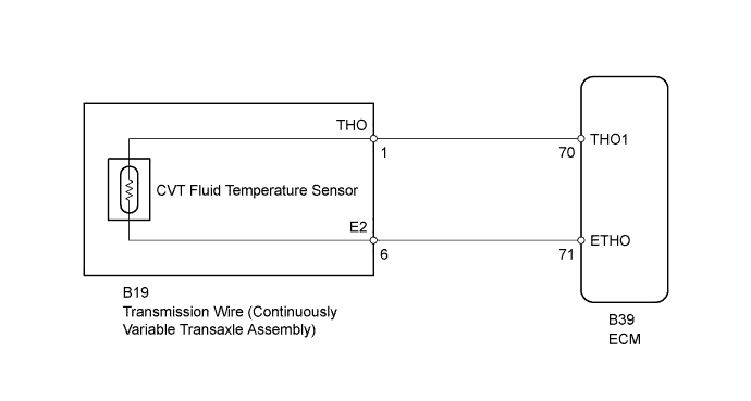
WIRING DIAGRAM
INSPECTION PROCEDURE
PROCEDURE
-
READ VALUE USING INTELLIGENT TESTER (A/T OIL TEMPERATURE 1)
-
Warm up the engine.
-
Turn the ignition switch off.
-
Connect the intelligent tester to the DLC3.
-
Turn the ignition switch to ON.
-
Turn the intelligent tester on.
-
Enter the following menus: Powertrain / Engine and ECT / Data List.
-
In accordance with the display on the tester, read the Data List.
Engine and ECT Tester Display Measurement Item/Range Normal Condition Diagnostic Note A/T Oil Temperature 1 CVT fluid temperature sensor value/
min.: -40°C (-40°F)
max.: 215°C (419°F)
-
After stall speed test: Approx. 80°C (176°F)
-
Equal to ambient temperature after cold soak
If the value is -40°C (-40°F) or 150°C (302°F) or more, the CVT fluid temperature sensor circuit is open or shorted. Result Result Proceed to Data displayed is not as specified under Normal Condition A Data displayed is as specified under Normal Condition B -
B 
A 
-
-
INSPECT TRANSMISSION WIRE (CVT FLUID TEMPERATURE SENSOR)
-
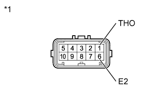
Text in Illustration *1 Component without harness connected
(Transmission Wire)
Disconnect the transmission wire connector.
-
Measure the resistance according to the value(s) in the table below.
Standard Resistance Tester Connection Condition Specified Condition 1 (THO) - 6 (E2) Always 79 Ω to 156 kΩ 1 (THO) - Body ground Always 10 kΩ or higher 6 (E2) - Body ground Always 10 kΩ or higher Tech Tips
If the resistance is outside the specified range at any of the CVT fluid temperatures shown in the table below, the driveability of the vehicle may be affected.
Resistance (Reference) CVT Fluid Temperature Specified Condition 10°C (50°F) 5 to 8 kΩ 25°C (77°F) 2.5 to 4.5 kΩ 110°C (230°F) 0.22 to 0.28 kΩ
NG
OK
-
-
CHECK HARNESS AND CONNECTOR (TRANSMISSION WIRE - ECM)
-
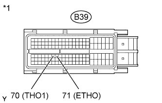
Text in Illustration *1 Front view of wire harness connector
(to ECM)
Disconnect the ECM connector.
-
Measure the resistance according to the value(s) in the table below.
Standard Resistance Tester Connection Condition Specified Condition B39-70 (THO1) - B39-71 (ETHO) Always 79 Ω to 156 kΩ B39-70 (THO1) - Body ground Always 10 kΩ or higher B39-71 (ETHO) - Body ground Always 10 kΩ or higher
NG 
REPAIR OR REPLACE HARNESS OR CONNECTOR
OK
-
-
REPLACE ECM
-
Replace the ECM Click here.
NEXT
-
-
PERFORM INITIALIZATION
Note
-
Performing reset memory will clear the learned values of both the yaw rate sensor (deceleration sensor 0 point calibration) and CVT oil pressure (CVT oil pressure calibration). Make sure to perform reset memory, yaw rate sensor 0 point calibration and CVT oil pressure calibration when replacing any of the parts shown in the following table:
Replaced Part
-
Continuously variable transaxle assembly
-
ECM
-
Oil pressure sensor
-
Yaw rate sensor
-
-
After performing reset memory, always perform yaw rate sensor (deceleration sensor 0 point) calibration first, and then CVT oil pressure calibration.
-
Always perform 0 point calibration with the vehicle on level ground.
-
Do not shake or vibrate the vehicle during 0 point calibration.
-
Using the intelligent tester, perform reset memory, deceleration sensor 0 point calibration and CVT oil pressure calibration Click here.
-
Check that no DTC is stored.
NEXT 
END
-
-
REPLACE ECM
-
Replace the ECM Click here.
NEXT
-
-
PERFORM INITIALIZATION
Note
-
Performing reset memory will clear the learned values of both the yaw rate sensor (deceleration sensor 0 point calibration) and CVT oil pressure (CVT oil pressure calibration). Make sure to perform reset memory, yaw rate sensor 0 point calibration and CVT oil pressure calibration when replacing any of the parts shown in the following table:
Replaced Part
-
Continuously variable transaxle assembly
-
ECM
-
Oil pressure sensor
-
Yaw rate sensor
-
-
After performing reset memory, always perform yaw rate sensor (deceleration sensor 0 point) calibration first, and then CVT oil pressure calibration.
-
Always perform 0 point calibration with the vehicle on level ground.
-
Do not shake or vibrate the vehicle during 0 point calibration.
-
Using the intelligent tester, perform reset memory, deceleration sensor 0 point calibration and CVT oil pressure calibration Click here.
-
Check that no DTC is stored.
NEXT
END
-
-
REPLACE CONTINUOUSLY VARIABLE TRANSAXLE ASSEMBLY
-
Replace the continuously variable transaxle assembly Click here.
NEXT
-
-
PERFORM INITIALIZATION
Note
-
Performing reset memory will clear the learned values of both the yaw rate sensor (deceleration sensor 0 point calibration) and CVT oil pressure (CVT oil pressure calibration). Make sure to perform reset memory, yaw rate sensor 0 point calibration and CVT oil pressure calibration when replacing any of the parts shown in the following table:
Replaced Part
-
Continuously variable transaxle assembly
-
ECM
-
Oil pressure sensor
-
Yaw rate sensor
-
-
After performing reset memory, always perform yaw rate sensor (deceleration sensor 0 point) calibration first, and then CVT oil pressure calibration.
-
Always perform 0 point calibration with the vehicle on level ground.
-
Do not shake or vibrate the vehicle during 0 point calibration.
-
Using the intelligent tester, perform reset memory, deceleration sensor 0 point calibration and CVT oil pressure calibration Click here.
-
Check that no DTC is stored.
NEXT
END
-