MANUAL TRANSAXLE ASSEMBLY INSTALLATION

Note
When the transaxle is removed, be sure to use a new clutch release with bearing cylinder and new installation bolts. Removal of the transaxle allows the compressed clutch release with bearing cylinder to return to its original position, and dust could damage the seal of the clutch release with bearing cylinder, possibly causing clutch fluid leaks.
-
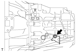
INSTALL SPEEDOMETER DRIVEN HOLE COVER SUB-ASSEMBLY
-
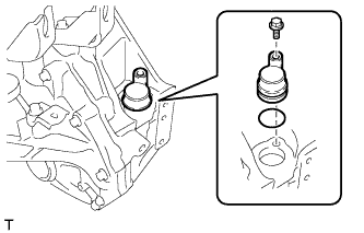
Coat a new O-ring with gear oil.
-
Install the O-ring to the speedometer driven hole cover sub-assembly.
-
Install the speedometer driven hole cover sub-assembly to the transaxle case with the bolt.
- Torque:
- 5.5 N*m { 56 kgf*cm, 49 in.*lbf }
-
-
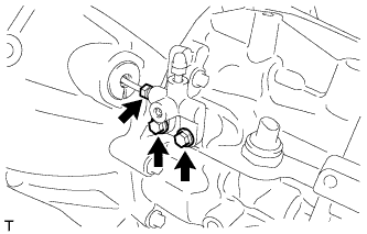
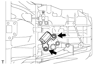
INSTALL CLUTCH RELEASE WITH BEARING CYLINDER ASSEMBLY
-
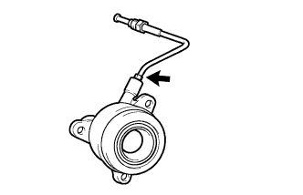
Temporarily install the clutch release cylinder to bleeder tube to a new clutch release with bearing cylinder assembly.
-
Clean and degrease all installation surfaces for the clutch release with bearing cylinder assembly.
-
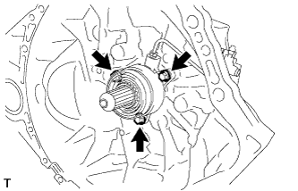
Install the clutch release with bearing cylinder assembly with 3 new bolts.
- Torque:
- 23 N*m { 229 kgf*cm, 17 ft.*lbf }
Note
-
The clutch release with bearing cylinder and installation bolts cannot be reused and must be replaced with new ones.
-
Clean and degrease all installation surfaces and make sure the clutch release with bearing cylinder fits securely with the transaxle during installation. The first bolt should be tightened by hand while holding the clutch release with bearing cylinder.
-
Make sure that none of the clutch spline grease adheres to the clutch release with bearing cylinder.
-
The clutch release with bearing cylinder cannot be disassembled.
-
Install the clutch tube boot to the manual transaxle assembly.
-
Temporarily install the clutch release cylinder to bleeder tube to the clutch release bleeder sub-assembly.
-
Temporarily install the clutch release bleeder sub-assembly with the 2 bolts.
-
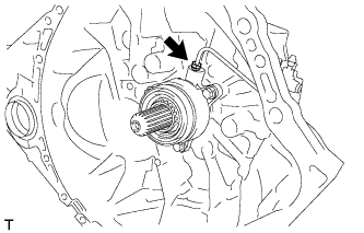
Using a union nut wrench, install the clutch release cylinder to bleeder tube.
- Torque:
- 15 N*m { 155 kgf*cm, 11 ft.*lbf }
Note
Use the formula to calculate special torque values for situations where a union nut wrench is combined with a torque wrench Click here.
-
Text in Illustration *1 Clutch spline grease Apply clutch spline grease to the input shaft spline.
Grease Toyota Genuine Clutch Spline Grease or equivalent
-
-
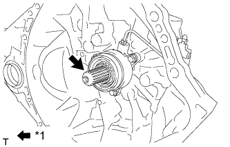
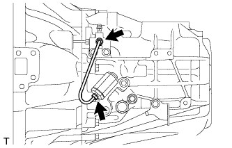
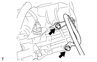
REMOVE CLUTCH RELEASE BLEEDER SUB-ASSEMBLY
-
Separate the clutch release cylinder to bleeder tube from the clutch release bleeder sub-assembly.
-
Remove the 2 bolts and clutch release bleeder sub-assembly.
-
-
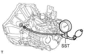
INSPECT CLUTCH PIPE LINE
-
Using SST, apply a pressure of 100 kPa (1.0 kgf/cm2, 15 psi) to the clutch pipe location shown in the illustration and confirm that pressure is maintained for 15 seconds or more.
- SST
- 09992-00242
If the pressure drops, replace the clutch release cylinder to bleeder tube.
-
-
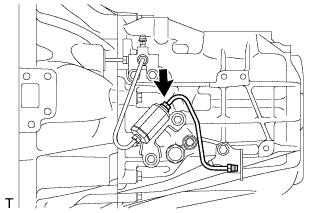
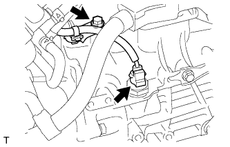
INSTALL CLUTCH RELEASE BLEEDER SUB-ASSEMBLY
-
Temporarily install the clutch release cylinder to bleeder tube to the clutch release bleeder sub-assembly.
-
Install the clutch release bleeder sub-assembly with the 2 bolts.
- Torque:
- 17 N*m { 170 kgf*cm, 12 ft.*lbf }
-
Using a union nut wrench, install the clutch release cylinder to bleeder tube.
- Torque:
- 15 N*m { 155 kgf*cm, 11 ft.*lbf }
Note
Use the formula to calculate special torque values for situations where a union nut wrench is combined with a torque wrench Click here.
-
-
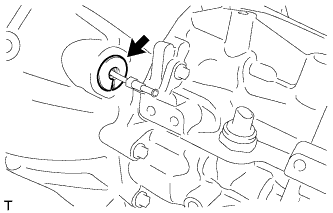
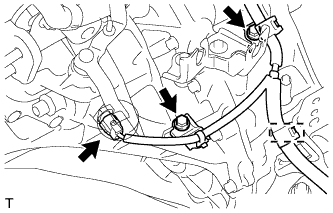
INSTALL CLUTCH FLEXIBLE HOSE BRACKET
-
Install the clutch flexible hose bracket to the manual transaxle with the bolt.
- Torque:
- 12 N*m { 122 kgf*cm, 9 ft.*lbf }
-
-
INSTALL CLUTCH ORIFICE ASSEMBLY
-
Install the 2 bolts and clutch orifice assembly.
- Torque:
- 12 N*m { 122 kgf*cm, 9 ft.*lbf }
-
-
INSTALL CLUTCH RELEASE BLEEDER TUBE
-
Using a union nut wrench, install the clutch release bleeder tube.
- Torque:
- 15 N*m { 155 kgf*cm, 11 ft.*lbf }
Note
Use the formula to calculate special torque values for situations where a union nut wrench is combined with a torque wrench Click here.
-
-
INSTALL ORIFICE TO FLEXIBLE HOSE TUBE
-
Using a union nut wrench, install the orifice to flexible hose tube.
- Torque:
- 15 N*m { 155 kgf*cm, 11 ft.*lbf }
Note
Use the formula to calculate special torque values for situations where a union nut wrench is combined with a torque wrench Click here.
-
-
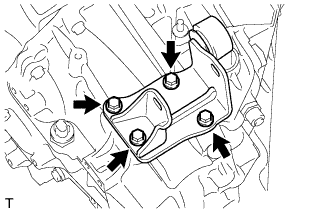
INSTALL REAR ENGINE MOUNTING BRACKET
-
Install the rear engine mounting bracket with the 4 bolts.
- Torque:
- 45 N*m { 459 kgf*cm, 33 ft.*lbf }
-
-
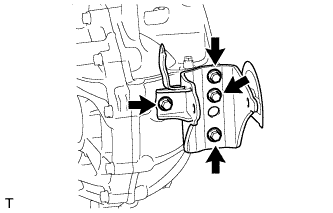
INSTALL ENGINE MOUNTING BRACKET LH
-
Apply adhesive to the 4 bolts.
Adhesive Toyota Genuine Adhesive 1324, Three Bond 1324 or equivalent -
Install the engine mounting bracket LH with the 4 bolts.
- Torque:
- 64 N*m { 653 kgf*cm, 47 ft.*lbf }
-
-
INSTALL FRONT ENGINE MOUNTING BRACKET
-
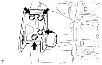
Install the front engine mounting bracket with the 4 bolts.
- Torque:
- 64 N*m { 653 kgf*cm, 47 ft.*lbf }
-
-
INSTALL MANUAL TRANSAXLE ASSEMBLY
-
Align the input shaft with the clutch disc and install the manual transaxle to the engine.
Note
-
Make sure that the dowel pins are not loose, bent, damaged or scratched and then install the transaxle onto the engine with the contact surfaces of the engine and transaxle flat against each other.
-
Insert the dowel pins into the dowel holes securely so that the end face of the transaxle assembly fits close against the engine assembly before tightening the bolts
-
-
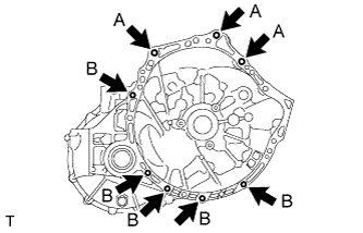
Install the 8 bolts.
- Torque:
- for bolt A
- 38 N*m { 388 kgf*cm, 28 ft.*lbf }
- for bolt B
- 40 N*m { 408 kgf*cm, 30 ft.*lbf }
-
Connect the neutral position switch connector and install the clamp and wire harness to the manual transaxle with the 2 bolts.
- Torque:
- 13 N*m { 130 kgf*cm, 9 ft.*lbf }
-
Connect the back-up light switch connector and install the wire harness to the manual transaxle with the bolt.
- Torque:
- 13 N*m { 130 kgf*cm, 9 ft.*lbf }
-
-
INSTALL ENGINE WIRE
-
Install the engine wire with the 2 bolts.
- Torque:
- 13 N*m { 130 kgf*cm, 9 ft.*lbf }
-
-
INSTALL STARTER ASSEMBLY
-
for 3ZR-FAE:
Install the starter assembly Click here.
-
for 3ZR-FE:
Install the starter assembly Click here.
-
-
INSTALL ENGINE ASSEMBLY WITH TRANSAXLE
-
for 3ZR-FAE:
Install the engine assembly with transaxle Click here.
-
for 3ZR-FE:
Install the engine assembly with transaxle Click here.
-
-
PERFORM CLUTCH ENGAGEMENT POINT LEARNING