SFI SYSTEM Fuel Injector Circuit
DESCRIPTION
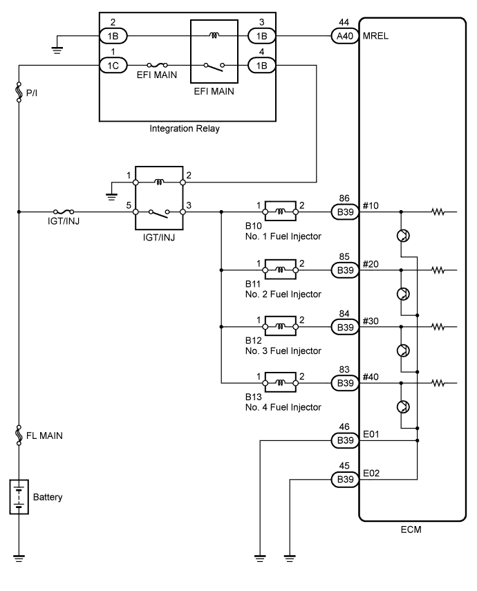
The fuel injectors are located on the intake manifold. They inject fuel into the cylinders based on the signals from the ECM.
WIRING DIAGRAM
INSPECTION PROCEDURE
Note
Inspect the fuses for circuits related to this system before performing the following inspection procedure.
PROCEDURE
-
CHECK FUEL INJECTOR (POWER SOURCE)
-
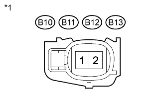
Text in Illustration *1 Front view of wire harness connector
(to Fuel Injector)
Disconnect the fuel injector connectors.
-
Turn the ignition switch to ON.
-
Measure the voltage according to the value(s) in the table below.
Standard Voltage Tester Connection Switch Condition Specified Condition B10-1 - Body ground Ignition switch ON 11 to 14 V B11-1 - Body ground Ignition switch ON 11 to 14 V B12-1 - Body ground Ignition switch ON 11 to 14 V B13-1 - Body ground Ignition switch ON 11 to 14 V -
Turn the ignition switch off.
-
Reconnect the fuel injector connectors.
NG 
INSPECT IGT/INJ RELAY Click here
OK 
-
-
INSPECT FUEL INJECTOR
-
Inspect the fuel injector Click here.
NG 
REPLACE FUEL INJECTOR Click here
OK
-
-
CHECK HARNESS AND CONNECTOR (FUEL INJECTOR - ECM)
-
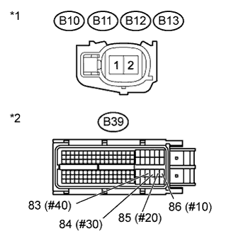
Text in Illustration *1 Front view of wire harness connector
(to Fuel Injector)
*1 Front view of wire harness connector
(to ECM)
Disconnect the fuel injector connectors.
-
Disconnect the ECM connector.
-
Measure the resistance according to the value(s) in the table below.
Standard Resistance (Check for open) Tester Connection Condition Specified Condition B10-2 - B39-86 (#10) Always Below 1 Ω B11-2 - B39-85 (#20) Always Below 1 Ω B12-2 - B39-84 (#30) Always Below 1 Ω B13-2 - B39-83 (#40) Always Below 1 Ω Standard Resistance (Check for short) Tester Connection Condition Specified Condition B10-2 or B39-86 (#10) - Body ground Always 10 kΩ or higher B11-2 or B39-85 (#20) - Body ground Always 10 kΩ or higher B12-2 or B39-84 (#30) - Body ground Always 10 kΩ or higher B13-2 or B39-83 (#40) - Body ground Always 10 kΩ or higher -
Reconnect the fuel injector connectors.
-
Reconnect the ECM connector.
NG
REPAIR OR REPLACE HARNESS OR CONNECTOR (FUEL INJECTOR - ECM)
OK 
REPLACE ECM Click here
-
-
INSPECT IGT/INJ RELAY
-
Remove the IGT/INJ relay from the engine room No. 1 relay block.
-
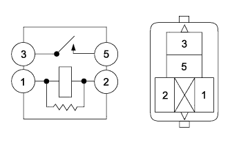
Measure the resistance according to the value(s) in the table below.
Standard Resistance Tester Connection Condition Specified Condition 3 - 5 Battery voltage is not applied to terminals 1 and 2 10 kΩ or higher 3 - 5 Battery voltage is applied to terminals 1 and 2 Below 1 Ω -
Reinstall the IGT/INJ relay.
NG
REPLACE IGT/INJ RELAY
OK
-
-
CHECK HARNESS AND CONNECTOR (IGT/INJ RELAY - BATTERY, BODY GROUND)
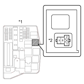
Text in Illustration *1 Engine Room No. 1 Relay Block *2 IGT/INJ Relay
-
Disconnect the cable from the negative (-) battery terminal.
-
Disconnect the cable from the positive (+) battery terminal.
-
Remove the IGT/INJ relay from the engine room No. 1 relay block.
-
Measure the resistance according to the value(s) in the table below.
Standard Resistance (Check for open) Tester Connection Condition Specified Condition IGT/INJ relay (5) - Positive battery cable Always Below 1 Ω IGT/INJ relay (1) - Body ground Always Below 1 Ω Standard Resistance (Check for short) Tester Connection Condition Specified Condition IGT/INJ relay (5) or Positive battery cable - Body ground Always 10 kΩ or higher -
Reinstall the IGT/INJ relay.
-
Reconnect the positive (+) battery cable.
-
Reconnect the negative (-) battery cable.
NG
REPAIR OR REPLACE HARNESS OR CONNECTOR (IGT/INJ RELAY - BATTERY, BODY GROUND)
OK
-
-
CHECK HARNESS AND CONNECTOR (IGT/INJ RELAY - FUEL INJECTOR)
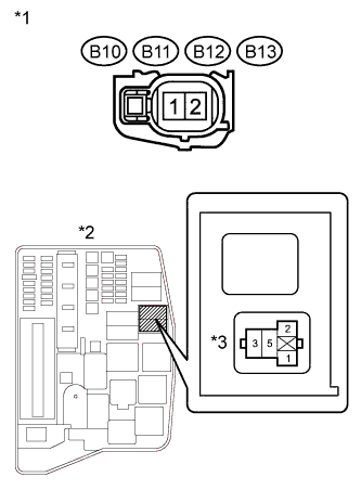
Text in Illustration *1 Front view of wire harness connector
(to Fuel Injector)
*2 Engine Room No. 1 Relay Block *3 IGT/INJ Relay
-
Disconnect the fuel injector connectors.
-
Remove the IGT/INJ relay from the engine room No. 1 relay block.
-
Measure the resistance according to the value(s) in the table below.
Standard Resistance (Check for open) Tester Connection Condition Specified Condition B10-1 - IGT/INJ relay (3) Always Below 1 Ω B11-1 - IGT/INJ relay (3) Always Below 1 Ω B12-1 - IGT/INJ relay (3) Always Below 1 Ω B13-1 - IGT/INJ relay (3) Always Below 1 Ω Standard Resistance (Check for short) Tester Connection Condition Specified Condition B10-1 or IGT/INJ relay (3) - Body ground Always 10 kΩ or higher B11-1 or IGT/INJ relay (3) - Body ground Always 10 kΩ or higher B12-1 or IGT/INJ relay (3) - Body ground Always 10 kΩ or higher B13-1 or IGT/INJ relay (3) - Body ground Always 10 kΩ or higher -
Reinstall the IGT/INJ relay.
-
Reconnect the fuel injector connector.
NG
REPAIR OR REPLACE HARNESS OR CONNECTOR (IGT/INJ RELAY - FUEL INJECTOR)
OK
-
-
CHECK HARNESS AND CONNECTOR (INTEGRATION RELAY (IG2 RELAY) - IGT/INJ RELAY)
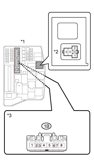
Text in Illustration *1 Engine Room No. 1 Relay Block *2 IGT/INJ Relay *3 Front view of wire harness connector
(to Integration Relay)
-
Remove the IGT/INJ relay from the engine room No. 1 relay block.
-
Remove the integration relay from the engine room No. 1 relay block.
-
Disconnect the integration relay connector.
-
Measure the resistance according to the value(s) in the table below.
Standard Resistance (Check for open) Tester Connection Condition Specified Condition IGT/INJ relay (2) - 1B-4 Always Below 1 Ω Standard Resistance (Check for short) Tester Connection Condition Specified Condition IGT/INJ relay (2) or 1B-4 - Body ground Always 10 kΩ or higher -
Reinstall the IGT/INJ relay.
-
Reconnect the integration relay connector.
-
Reinstall the integration relay.
NG
REPAIR OR REPLACE HARNESS OR CONNECTOR (INTEGRATION RELAY (IG2 RELAY) - IGT/INJ RELAY)
OK
GO TO ECM POWER SOURCE CIRCUIT Click here
-