SFI SYSTEM, Diagnostic DTC:P0351, P0352, P0353, P0354

| DTC Code | DTC Name |
|---|---|
| P0351 | Ignition Coil "A" Primary / Secondary Circuit |
| P0352 | Ignition Coil "B" Primary / Secondary Circuit |
| P0353 | Ignition Coil "C" Primary / Secondary Circuit |
| P0354 | Ignition Coil "D" Primary / Secondary Circuit |
DESCRIPTION
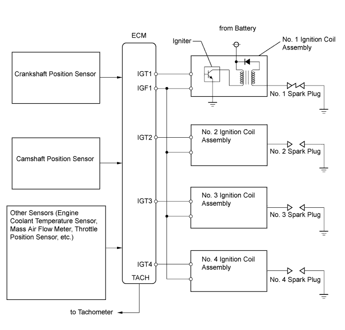
A Direct Ignition System (DIS) is used on this vehicle to enhance ignition accuracy and suppress high voltage losses.
The DIS is an ignition system in which each cylinder is ignited by one ignition coil assembly. The ECM determines the ignition timing and transmits the ignition (IGT) signals to each cylinder. Based on the IGT signals, the ECM turns the power transistor inside the igniter on and off, turning the current to the primary coil on and off. When the current to the primary coil is cut off, a voltage is generated in the secondary coil and then applied to the spark plugs, causing them to spark inside the cylinders. At the same time, the igniter sends back the ignition confirmation (IGF) signal to the ECM.
| DTC No. | DTC Detection Condition | Trouble Area |
|---|---|---|
| P0351 P0352 P0353 P0354 |
No IGF signal is sent to the ECM while the engine is running (1 trip detection logic). |
|
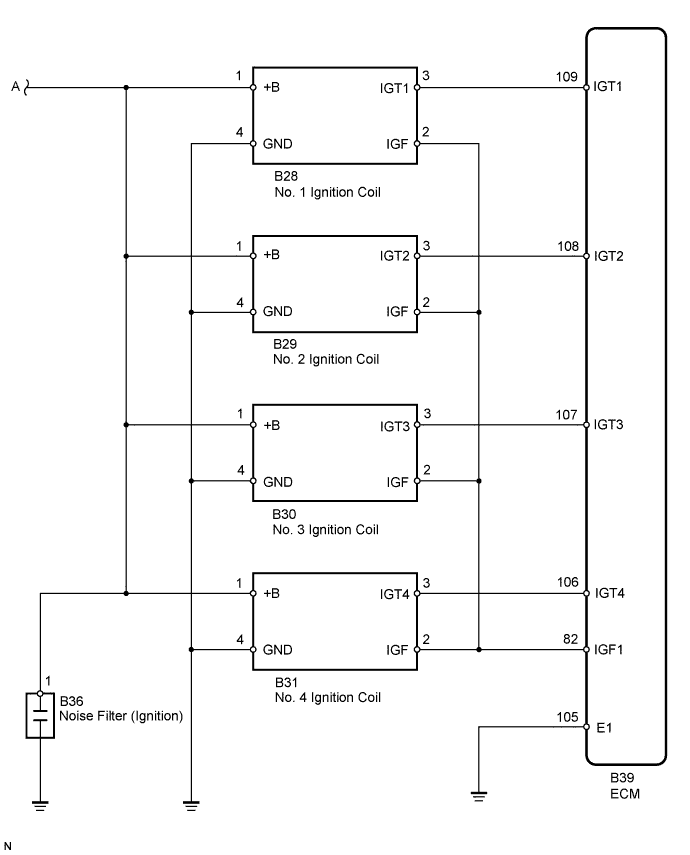
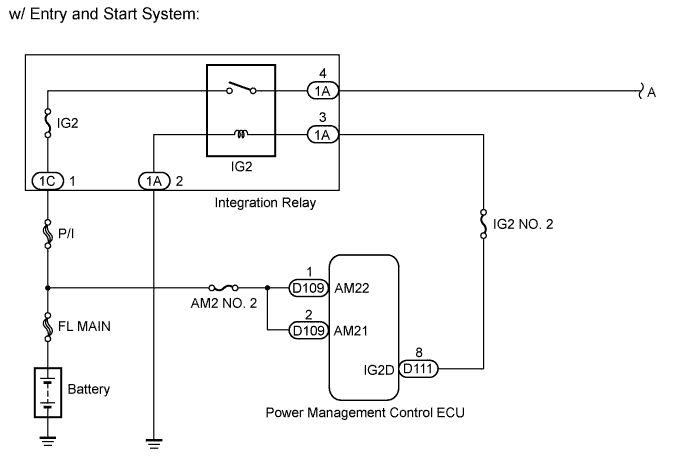
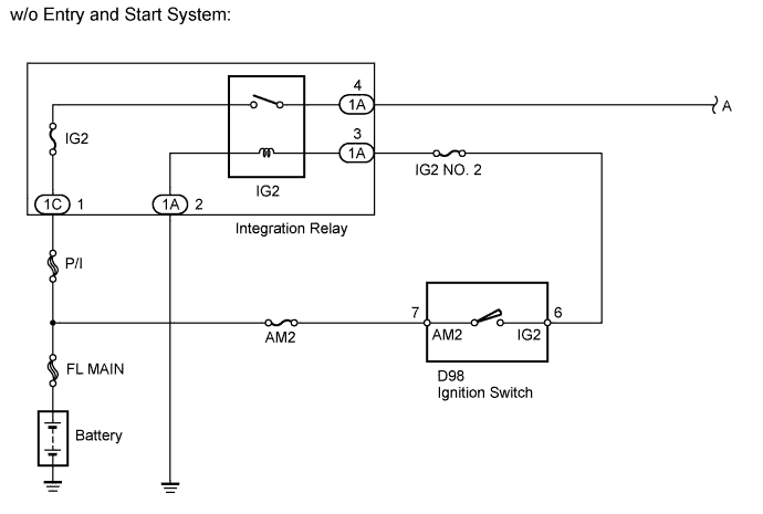
WIRING DIAGRAM
INSPECTION PROCEDURE
Tech Tips
-
The following inspection procedure is for the No. 1 cylinder. If any of the other cylinders are malfunctioning, inspect their circuits by referring to the following procedure.
-
If DTC P0351 is output, check the ignition coil assembly No. 1 circuit.
-
If DTC P0352 is output, check the ignition coil assembly No. 2 circuit.
-
If DTC P0353 is output, check the ignition coil assembly No. 3 circuit.
-
If DTC P0354 is output, check the ignition coil assembly No. 4 circuit.
-
Read freeze frame data using the intelligent tester. Freeze frame data records the engine condition when malfunctions are detected. When troubleshooting, freeze frame data can help determine if the vehicle was moving or stationary, if the engine was warmed up or not, if the air fuel ratio was lean or rich, and other data from the time the malfunction occurred.
PROCEDURE
-
CHECK DTC OUTPUT
-
Connect the intelligent tester to the DLC3.
-
Turn the ignition switch to ON.
-
Turn the tester on.
-
Enter the following menus: Powertrain / Engine and ECT / DTC.
-
Read the DTCs.
Result Result Proceed to DTC P0351, P0352, P0353 or P0354 is output A DTC P0351, P0352, P0353 and P0354 are output B
B 
CHECK HARNESS AND CONNECTOR (IGNITION COIL ASSEMBLY - BODY GROUND) Click here
A 
-
-
CHECK WHETHER DTC OUTPUT RECURS (DTC P0351, P0352, P0353 OR P0354)
-
Connect the intelligent tester to the DLC3.
-
Turn the ignition switch to ON.
-
Turn the tester on.
-
Clear the DTCs Click here.
-
Shuffle the arrangement of the ignition coil assemblies (among No. 1 to No. 4 cylinders).
Note
Do not shuffle the connectors.
-
Perform a simulation test.
-
Check the DTCs output to the tester.
Result Result Proceed to Same DTC output A Different ignition coil assembly DTC output B
B 
REPLACE IGNITION COIL ASSEMBLY Click here
A
-
-
CHECK IGNITION COIL ASSEMBLY (POWER SOURCE)
-
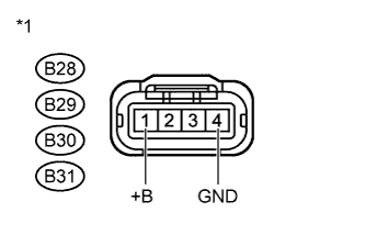
Text in Illustration *1 Front view of wire harness connector
(to Ignition Coil Assembly)
Disconnect the ignition coil assembly connectors.
-
Measure the voltage according to the value(s) in the table below.
Standard Voltage Tester Connection Switch Condition Specified Condition B28-1 (+B) - B28-4 (GND) Ignition switch ON 11 to 14 V B29-1 (+B) - B29-4 (GND) Ignition switch ON 11 to 14 V B30-1 (+B) - B30-4 (GND) Ignition switch ON 11 to 14 V B31-1 (+B) - B31-4 (GND) Ignition switch ON 11 to 14 V -
Reconnect the ignition coil assembly connectors.
NG
CHECK HARNESS AND CONNECTOR (IGNITION COIL ASSEMBLY - INTEGRATION RELAY [IG2]) Click here
OK
-
-
CHECK HARNESS AND CONNECTOR (IGNITION COIL ASSEMBLY - ECM)
-
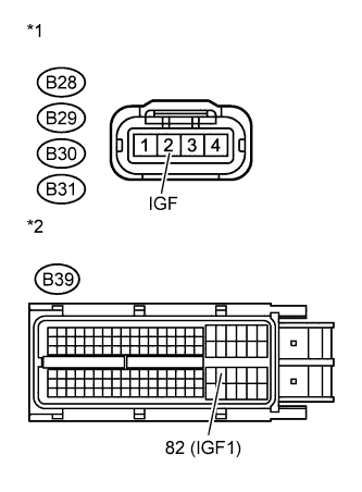
Text in Illustration *1 Front view of wire harness connector
(to Ignition Coil Assembly)
*2 Front view of wire harness connector
(to ECM)
Disconnect the ignition coil assembly connectors.
-
Disconnect the ECM connector.
-
Measure the resistance according to the value(s) in the table below.
Standard Resistance (Check for Open) Tester Connection Condition Specified Condition B28-2 (IGF) - B39-82 (IGF1) Always Below 1 Ω B29-2 (IGF) - B39-82 (IGF1) Always Below 1 Ω B30-2 (IGF) - B39-82 (IGF1) Always Below 1 Ω B31-2 (IGF) - B39-82 (IGF1) Always Below 1 Ω Standard Resistance (Check for Short) Tester Connection Condition Specified Condition B28-2 (IGF) or B39-82 (IGF1) - Body ground Always 10 kΩ or higher B29-2 (IGF) or B39-82 (IGF1) - Body ground Always 10 kΩ or higher B30-2 (IGF) or B39-82 (IGF1) - Body ground Always 10 kΩ or higher B31 (IGF) or B39-82 (IGF1) - Body ground Always 10 kΩ or higher -
Reconnect the ECM connector.
-
Reconnect the ignition coil assembly connectors.
NG
REPAIR OR REPLACE HARNESS OR CONNECTOR (IGNITION COIL ASSEMBLY - ECM)
OK
-
-
CHECK HARNESS AND CONNECTOR (IGNITION COIL ASSEMBLY - ECM)
-
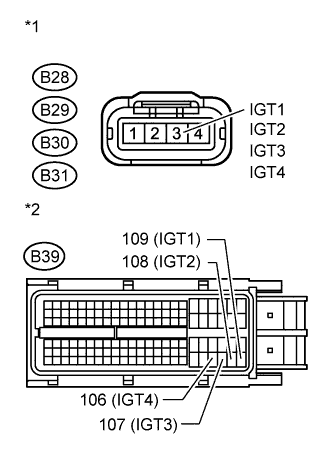
Text in Illustration *1 Front view of wire harness connector
(to Ignition Coil Assembly)
*2 Front view of wire harness connector
(to ECM)
Disconnect the ignition coil assembly connectors.
-
Disconnect the ECM connector.
-
Measure the resistance according to the value(s) in the table below.
Standard Resistance (Check for Open) Tester Connection Condition Specified Condition B28-3 (IGT1) - B39-109 (IGT1) Always Below 1 Ω B29-3 (IGT2) - B39-108 (IGT2) Always Below 1 Ω B30-3 (IGT3) - B39-107 (IGT3) Always Below 1 Ω B31-3 (IGT4) - B39-106 (IGT4) Always Below 1 Ω Standard Resistance (Check for Short) Tester Connection Condition Specified Condition B28-3 (IGT1) or B39-109 - Body ground Always 10 kΩ or higher B29-3 (IGT2) or B39-108 (IGT2) - Body ground Always 10 kΩ or higher B30-3 (IGT3) or B39-107 (IGT3) - Body ground Always 10 kΩ or higher B31-3 (IGT4) or B39-106 (IGT4) - Body ground Always 10 kΩ or higher -
Reconnect the ECM connector.
-
Reconnect the ignition coil assembly connectors.
NG
REPAIR OR REPLACE HARNESS OR CONNECTOR (IGNITION COIL ASSEMBLY - ECM)
OK 
REPLACE ECM Click here
-
-
CHECK HARNESS AND CONNECTOR (IGNITION COIL ASSEMBLY - BODY GROUND)
-
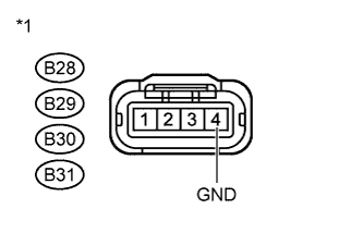
Text in Illustration *1 Front view of wire harness connector
(to Ignition Coil Assembly)
Disconnect the ignition coil assembly connectors.
-
Measure the resistance according to the value(s) in the table below.
Standard Resistance Tester Connection Condition Specified Condition B28-4 (GND) - Body ground Always Below 1 Ω B29-4 (GND) - Body ground Always Below 1 Ω B30-4 (GND) - Body ground Always Below 1 Ω B31-4 (GND) - Body ground Always Below 1 Ω -
Reconnect the ignition coil assembly connectors.
NG
REPAIR OR REPLACE HARNESS OR CONNECTOR (IGNITION COIL ASSEMBLY - BODY GROUND)
OK
-
-
CHECK HARNESS AND CONNECTOR (IGNITION COIL ASSEMBLY - INTEGRATION RELAY [IG2])
-
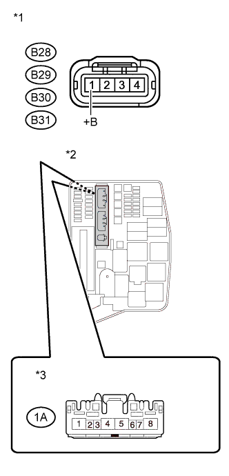
Text in Illustration *1 Front view of wire harness connector
(to Ignition Coil Assembly)
*2 Engine Room No. 1 Relay Block *3 Front view of wire harness connector
(to Integration Relay)
Disconnect the ignition coil assembly connectors.
-
Remove the integration relay from the engine room No. 1 relay block.
-
Disconnect the integration relay connector.
-
Measure the resistance according to the value(s) in the table below.
Standard Resistance (Check for Open) Tester Connection Condition Specified Condition B28-1 (+B) - 1A-4 Always Below 1 Ω B29-1 (+B) - 1A-4 Always Below 1 Ω B30-1 (+B) - 1A-4 Always Below 1 Ω B31-1 (+B) - 1A-4 Always Below 1 Ω Standard Resistance (Check for Short) Tester Connection Condition Specified Condition B28-1 (+B) or 1A-4 - Body ground Always 10 kΩ or higher B29-1 (+B) or 1A-4 - Body ground Always 10 kΩ or higher B30-1 (+B) or 1A-4 - Body ground Always 10 kΩ or higher B31-1 (+B) or 1A-4 - Body ground Always 10 kΩ or higher -
Reconnect the integration relay connector.
-
Reinstall the integration relay.
-
Reconnect the ignition coil assembly connectors.
NG
REPAIR OR REPLACE HARNESS OR CONNECTOR (IGNITION COIL ASSEMBLY - INTEGRATION RELAY [IG2])
OK
CHECK ECU POWER SOURCE CIRCUIT Click here
-