ENGINE ASSEMBLY INSTALLATION

Note
for Manual Transaxle:
When the transaxle is removed, be sure to use a new clutch release with bearing cylinder and new installation bolts. Removal of the transaxle allows the compressed clutch release with bearing cylinder to return to its original position, and dust could damage the seal of the clutch release with bearing cylinder, possibly causing clutch fluid leaks.
-
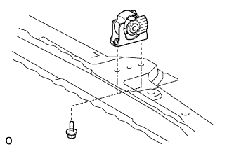
INSTALL ENGINE MOUNTING INSULATOR SUB-ASSEMBLY LH
Tech Tips
Perform this procedure only when replacement of the engine mounting insulator is necessary.
-
Install the engine mounting insulator with the 4 bolts.
- Torque:
- 95 N*m { 969 kgf*cm, 70 ft.*lbf }
-
-
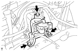
INSTALL ENGINE MOUNTING INSULATOR SUB-ASSEMBLY RH
Tech Tips
Perform this procedure only when replacement of the engine mounting insulator is necessary.
-
Install the engine mounting insulator with the 3 bolts.
- Torque:
- 95 N*m { 969 kgf*cm, 70 ft.*lbf }
-
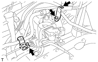
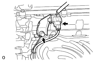
Install the 2 cooler pipe brackets with the 2 bolts and nut.
- Torque:
- 9.8 N*m { 100 kgf*cm, 87 in.*lbf }
-
Connect the cooler pipe clamp.
-
-
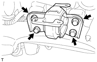
INSTALL REAR ENGINE MOUNTING INSULATOR
Tech Tips
Perform this procedure only when replacement of the engine mounting insulator is necessary.
-
Install the engine mounting insulator with the 2 bolts and 2 nuts.
- Torque:
- 95 N*m { 969 kgf*cm, 70 ft.*lbf }
-
-
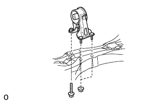
INSTALL FRONT ENGINE MOUNTING INSULATOR
Tech Tips
Perform this procedure only when replacement of the engine mounting insulator is necessary.
-
Install the engine mounting insulator with the 2 bolts.
- Torque:
- 95 N*m { 969 kgf*cm, 70 ft.*lbf }
-
-
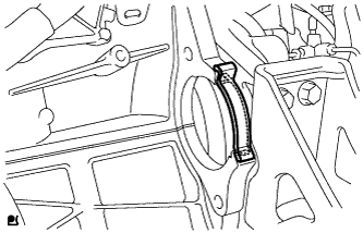
INSTALL ENGINE HANGER
-
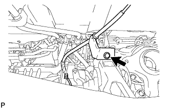
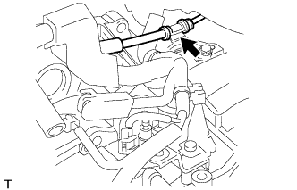
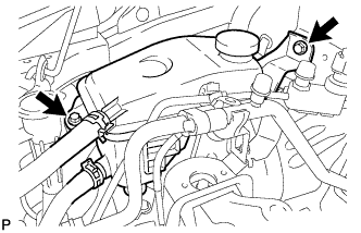
Disconnect the air fuel ratio sensor connector and remove the bolt and air fuel ratio sensor bracket.
-
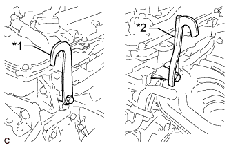
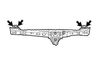
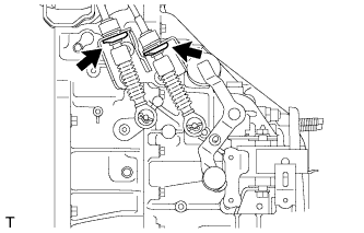
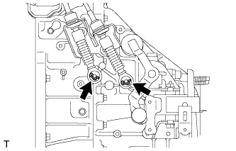
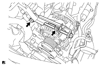
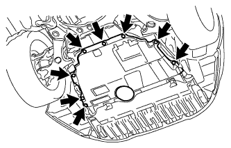
Text in Illustration *1 No. 1 Engine Hanger *2 No. 2 Engine Hanger Install the 2 engine hangers with 2 bolts as shown in the illustration.
- Torque:
- 43 N*m { 438 kgf*cm, 32 ft.*lbf }
Tech Tips
No. 1 Engine Hanger 12281-37021 No. 2 Engine Hanger 12282-37011 Bolt 91552-81050 -
Attach an engine sling device and hang the engine with a chain block.
-
-
REMOVE ENGINE STAND
-
Attach a sling device and hang the engine with a chain block.
-
Lift the engine and remove it from the engine stand.
-
-
INSTALL ENGINE WIRE
-
Install the engine wire to the engine.
-
-
INSTALL CLUTCH RELEASE WITH BEARING CYLINDER ASSEMBLY (for Manual Transaxle)
-
Install the clutch release with bearing cylinder assembly Click here.
-
-
INSTALL DRIVE PLATE AND RING GEAR SUB-ASSEMBLY (for CVT)
-
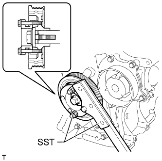
Using SST, hold the crankshaft.
- SST
- 09330-00021
- 09213-58014 ( 91551-80840 )
-
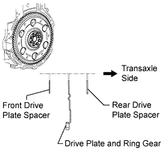
Install the front spacer, drive plate and rear spacer onto the crankshaft.
-
Clean the bolts and bolt holes.
-
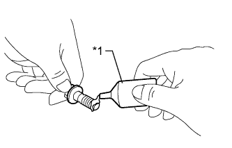
Apply adhesive to 2 or 3 threads at the end of the 8 bolts.
Text in Illustration *1 Adhesive Adhesive Toyota Genuine Adhesive 1324, Three Bond 1324 or equivalent -
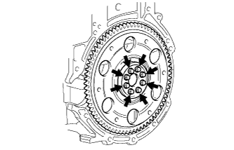
Uniformly tighten the 8 bolts.
- Torque:
- 88 N*m { 897 kgf*cm, 65 ft.*lbf }
-
-
INSTALL FLYWHEEL SUB-ASSEMBLY (for Manual Transaxle)
-
Using SST, hold the crankshaft.
- SST
- 09330-00021
- 09213-58014 ( 91551-80840 )
-
Clean the bolts and bolt holes.
-
Apply adhesive to 2 or 3 threads at the end of the 8 bolts.
Text in Illustration *1 Adhesive Adhesive Toyota Genuine Adhesive 1324, Three Bond 1324 or equivalent -
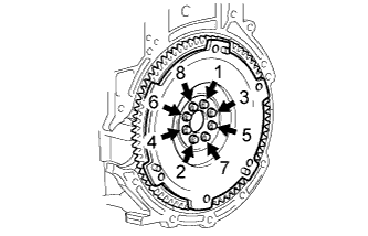
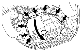
Uniformly install and tighten the 8 bolts in several steps in the sequence shown in the illustration.
- Torque:
- 49 N*m { 500 kgf*cm, 36 ft.*lbf }
-
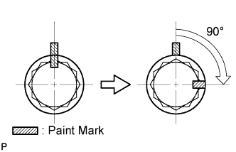
Mark the top of the bolts with paint.
-
Retighten the 8 bolts an additional 90° in the same sequence.
-
Check that the paint marks are now at a 90° angle to the top.
-
-
INSTALL CLUTCH DISC ASSEMBLY (for Manual Transaxle)
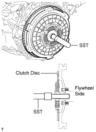
-
Insert SST into the clutch disc assembly, and then attach them both to the flywheel sub-assembly.
- SST
- 09301-00210
Note
Insert the clutch disc assembly in the correct direction.
-
-
INSTALL CLUTCH COVER ASSEMBLY (for Manual Transaxle)
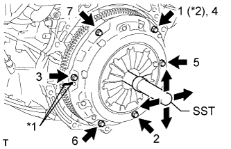
Text in Illustration *1 Matchmark *2 Temporarily Install
-
Align the matchmark on the clutch cover assembly with the one on the flywheel sub-assembly.
-
Following the order shown in the illustration, tighten the 6 bolts, starting with the bolt located near the knock pin at the top.
- SST
- 09301-00210
- Torque:
- 19 N*m { 195 kgf*cm, 14 ft.*lbf }
Tech Tips
-
Following the order in the illustration, tighten the bolts evenly one at a time.
-
Move SST up and down, right and left lightly after checking that the clutch disc assembly is in the center, and tighten the bolts.
-
-
INSPECT AND ADJUST CLUTCH COVER ASSEMBLY (for Manual Transaxle)
-
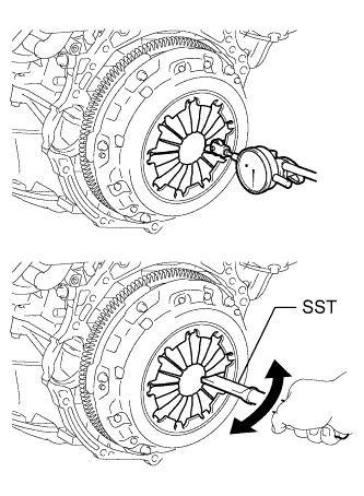
Using a dial indicator with a roller instrument, check the diaphragm spring tip alignment.
Maximum non-alignment 0.5 mm (0.0196 in.) If the alignment is more than the maximum, using SST, adjust the diaphragm spring tip alignment.
- SST
- 09333-00013
-
-
INSTALL CONTINUOUSLY VARIABLE TRANSAXLE ASSEMBLY (for CVT)
-
Install the continuously variable transaxle assembly Click here.
-
-
INSTALL MANUAL TRANSAXLE ASSEMBLY (for Manual Transaxle)
-
Install the manual transaxle assembly Click here.
-
-
INSTALL FLYWHEEL HOUSING SIDE COVER
-
Install the flywheel housing side cover to the cylinder block.
-
-
INSTALL STARTER ASSEMBLY
-
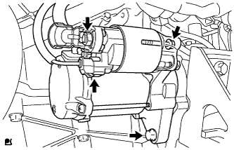
Install the starter with the 2 bolts.
- Torque:
- 37 N*m { 380 kgf*cm, 27 ft.*lbf }
-
Connect the connector.
-
Connect the starter wire with the nut.
- Torque:
- 9.8 N*m { 100 kgf*cm, 87 in.*lbf }
-
Connect the terminal cap.
-
-
TEMPORARILY INSTALL FRONT SUSPENSION CROSSMEMBER SUB-ASSEMBLY
-
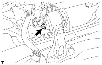
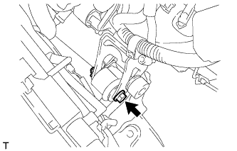
Temporarily install the rear engine mounting insulator to the engine mounting bracket with the through bolt.
-
-
INSTALL ENGINE ASSEMBLY WITH TRANSAXLE
-
Place the engine on an engine lifter.
Tech Tips
Place the engine on wooden blocks or equivalent so that the engine is level.
-
Operate the engine lifter and install the engine to the vehicle.
CAUTION:
Do not raise the engine more than necessary. If the engine is raised excessively, the vehicle may also be lifted up.
Note
-
Make sure that the engine is clear of all wiring and hoses.
-
While raising the engine into the vehicle, do not allow it to contact the vehicle.
-
-
Temporarily install the front suspension crossmember with 2 new bolts.
-
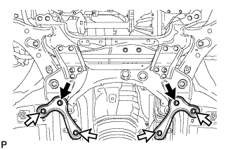
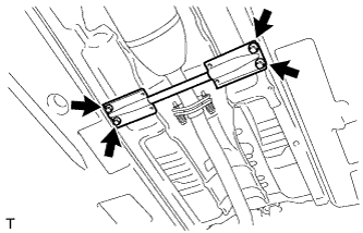
Temporarily install the member brace rear RH and LH with 2 new bolts and the 4 bolts.
Text in Illustration 
New Bolt 
Bolt -
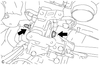
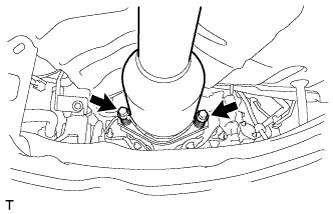
Install the engine mounting insulator LH with the through bolt and nut.
- Torque:
- 56 N*m { 571 kgf*cm, 41 ft.*lbf }
-
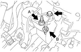
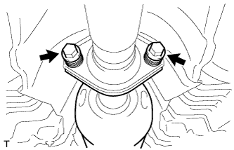
Install the engine mounting insulator RH with the bolt and 2 nuts.
- Torque:
- for bolt and nut A
- 95 N*m { 969 kgf*cm, 70 ft.*lbf }
- for nut B
- 52 N*m { 530 kgf*cm, 38 ft.*lbf }
-
Tighten the 2 front suspension member bolts.
- Torque:
- 137 N*m { 1397 kgf*cm, 101 ft.*lbf }
-
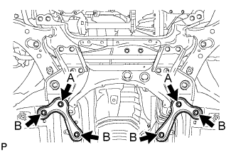
Tighten the 6 member brace rear bolts.
- Torque:
- for bolt A
- 137 N*m { 1397 kgf*cm, 101 ft.*lbf }
- for bolt B
- 93 N*m { 948 kgf*cm, 69 ft.*lbf }
-
Remove the 2 bolts and 2 engine hangers.
-
Install the air fuel ratio sensor bracket with the bolt. Then connect the air fuel ratio sensor connector.
- Torque:
- 60 N*m { 612 kgf*cm, 44 ft.*lbf }
-
-
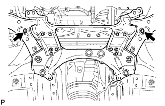
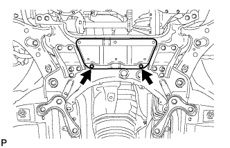
INSTALL FRONT CROSSMEMBER SUB-ASSEMBLY
-
Temporarily install the front crossmember with the 4 bolts.
-
Temporarily install the front engine mounting insulator to the front engine mounting bracket with the bolt and nut.
-
Tighten the 4 front crossmember bolts.
- Torque:
- 96 N*m { 979 kgf*cm, 71 ft.*lbf }
-
Tighten the front engine mounting insulator bolt and nut.
- Torque:
- 145 N*m { 1479 kgf*cm, 107 ft.*lbf }
-
-
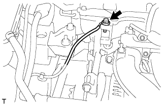
TIGHTEN FRONT SUSPENSION CROSSMEMBER SUB-ASSEMBLY
-
Tighten the rear engine mounting insulator bolt.
- Torque:
- 95 N*m { 969 kgf*cm, 70 ft.*lbf }
-
-
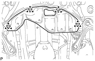
INSTALL FRONT SUSPENSION MEMBER REINFORCEMENT LH
-
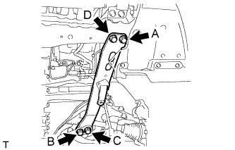
Install the reinforcement with the 4 bolts.
- Torque:
- 96 N*m { 979 kgf*cm, 71 ft.*lbf }
Note
Tighten the bolts in the order of C, B, D and A.
-
-
INSTALL FRONT SUSPENSION MEMBER REINFORCEMENT RH
-
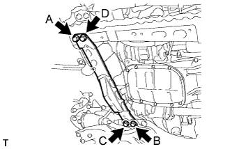
Install the reinforcement with the 4 bolts.
- Torque:
- 96 N*m { 979 kgf*cm, 71 ft.*lbf }
Note
Tighten the bolts in the order of C, B, D and A.
-
-
INSTALL DRIVE PLATE AND TORQUE CONVERTER SETTING BOLT (for CVT)
-
Apply a few drops of adhesive to 2 or 3 threads of the 6 torque converter setting bolt tips.
Adhesive Toyota Genuine Adhesive 1324, Three Bond 1324 or equivalent -
Turn the crankshaft to gain access to the installation locations of the 6 torque converter setting bolts and install each bolt while holding the crankshaft pulley bolt with a wrench.
- Torque:
- 41 N*m { 418 kgf*cm, 30 ft.*lbf }
Note
Install the black bolt first, and then the 5 silver bolts.
-
Install the flywheel housing under cover.
-
-
INSTALL FRONT DRIVE SHAFT ASSEMBLY LH
-
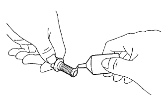
Coat the spline of the inboard joint shaft with oil.
Tech Tips
Be sure to use the same type of oil that is used for the transaxle.
-
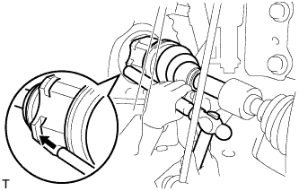
Align the shaft splines and tap in the drive shaft with a brass bar and hammer.
Note
-
Make sure that the snap ring opening is facing downwards when installing the drive shaft.
-
Be careful not to damage the oil seal, boot or dust cover.
-
-
-
INSTALL FRONT DRIVE SHAFT ASSEMBLY RH
-
Coat the spline of the inboard joint shaft with gear oil.
-
Align the shaft splines and securely insert the drive shaft.
-
Install the 2 bearing bracket bolts.
- Torque:
- 64 N*m { 650 kgf*cm, 47 ft.*lbf }
Note
Do not damage the oil seal, boot or dust cover.
-
-
INSTALL FRONT AXLE ASSEMBLY LH
-
Install the front axle assembly LH Click here.
-
-
INSTALL FRONT AXLE ASSEMBLY RH
Tech Tips
Use the same procedures described for the LH side.
-
CONNECT FRONT STABILIZER LINK ASSEMBLY LH
-
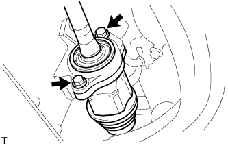
Connect the front stabilizer link assembly to the front shock absorber with coil spring with the nut.
- Torque:
- 74 N*m { 755 kgf*cm, 55 ft.*lbf }
Tech Tips
If the ball joint turns together with the nut, use a 6 mm hexagon wrench to hold the stud bolt.
-
-
CONNECT FRONT STABILIZER LINK ASSEMBLY RH
Tech Tips
Use the same procedures described for the LH side.
-
INSTALL FRONT AXLE SHAFT NUT LH
-
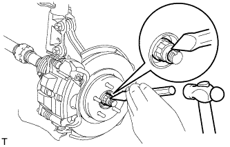
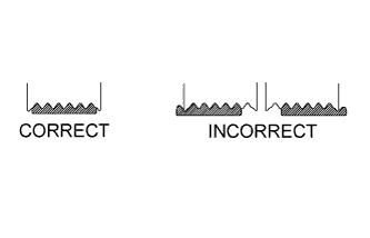
Using a chisel and a hammer, stake the front axle shaft nut.
-
-
INSTALL FRONT AXLE SHAFT NUT RH
Tech Tips
Use the same procedures described for the LH side.
-
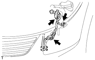
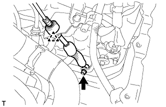
INSTALL FRONT EXHAUST PIPE ASSEMBLY
-
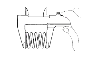
Using a vernier caliper, measure the free length of the compression springs.
Minimum Free Length Item Specified Condition Front side compression spring 41.5 mm (1.63 in.) Rear side compression spring 38.5 mm (1.52 in.) If the free length is less than the minimum, replace the compression spring.
-
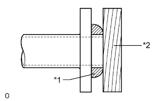
Text in Illustration *1 Gasket *2 Wooden Block Using a plastic-faced hammer and wooden block, tap in a new gasket until its surface is flush with the exhaust manifold.
Note
-
Be sure to install the gasket so that it faces the correct direction.
-
Do not reuse the gasket.
-
Do not damage the gasket.
-
When connecting the exhaust pipe, do not push in the gasket with the exhaust pipe.
-
-
Install the 2 exhaust pipe supports, and then install the front exhaust pipe assembly with the 2 compression springs and 2 bolts.
- Torque:
- 43 N*m { 438 kgf*cm, 32 ft.*lbf }
-
Text in Illustration *1 Gasket *2 Wooden Block Using a plastic-faced hammer and wooden block, tap in a new gasket until its surface is flush with the front exhaust pipe assembly.
Note
-
Be sure to install the gasket so that it faces the correct direction.
-
Do not reuse the gasket.
-
Do not damage the gasket.
-
When connecting the exhaust pipe, do not push in the gasket with the exhaust pipe.
-
-
Connect the front exhaust pipe assembly to the tailpipe assembly with the 2 compression springs and 2 bolts.
- Torque:
- 43 N*m { 438 kgf*cm, 32 ft.*lbf }
-
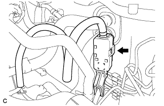
Connect the heated oxygen sensor connector.
-
Attach the clamp to connect the heated oxygen sensor wire harness.
-
-
INSTALL FRONT CENTER FLOOR BRACE
-
Install the floor brace with the 4 bolts.
- Torque:
- 51 N*m { 520 kgf*cm, 38 ft.*lbf }
-
-
CONNECT NO. 1 STEERING COLUMN HOLE COVER SUB-ASSEMBLY
-
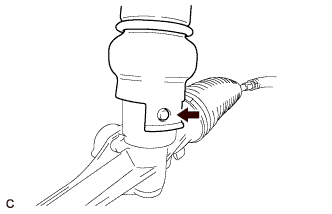
Align the round hole in the No. 1 steering column hole cover with the protrusion of the steering link and install the cover.
-
-
CONNECT NO. 2 STEERING INTERMEDIATE SHAFT ASSEMBLY
-
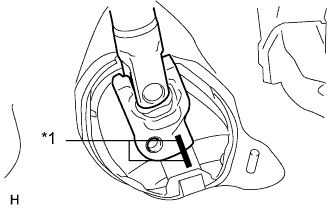
Text in Illustration *1 Matchmark Align the matchmarks on the No. 2 steering intermediate shaft assembly and steering intermediate shaft assembly.
-
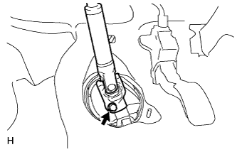
Install the bolt.
- Torque:
- 35 N*m { 360 kgf*cm, 26 ft.*lbf }
-
-
INSTALL COLUMN HOLE COVER SILENCER SHEET
-
Install the column hole cover silencer sheet with the 2 clips.
-
Install the floor carpet.
-
-
CONNECT WIRE HARNESS AND HOSE
-
Connect the vacuum hose.
-
Connect the connector tube hose.
-
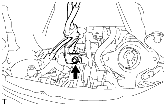
Connect the engine wire with the bolt.
- Torque:
- 29 N*m { 296 kgf*cm, 21 ft.*lbf }
-
Connect the engine wire with the 2 bolts and clamp.
- Torque:
- 8.4 N*m { 86 kgf*cm, 74 in.*lbf }
-
Connect the connector to the battery current sensor.
-
Attach the 2 clamps to install the wire harness, and then install the 2 nuts.
- Torque:
- 8.4 N*m { 86 kgf*cm, 74 in.*lbf }
-
Connect the 3 wire harness connectors to the engine room No. 1 junction block.
-
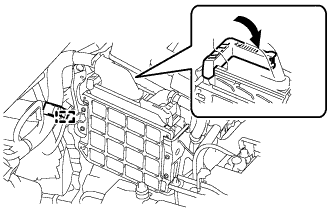
Connect the ECM connector and lower the lever.
Note
-
When connecting the connector, make sure that dirt, water or other foreign matter does not get caught between the connector and other parts.
-
Make sure that the lever is securely lowered.
-
-
Connect the wire harness clamp.
-
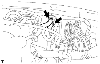
for CVT:
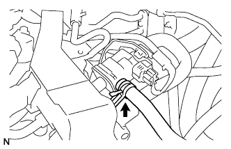
Connect the 2 oil cooler hoses to the oil cooler tube.
-
-
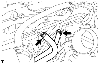
CONNECT HEATER WATER HOSE
-
Connect the 2 heater water hoses.
-
-
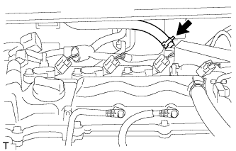
CONNECT FUEL TUBE SUB-ASSEMBLY
-
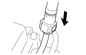
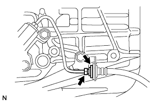
Connect the fuel tube connector and fuel pipe.
Note
Align the fuel tube connector with the pipe, and then push the fuel tube connector on until the retainer makes a "click" sound. If the connection is tight, apply a small amount of engine oil to the tip of the pipe. After connecting the connector, pull the pipe and connector to make sure that they are securely connected.
-
Attach the claw to install the No. 1 fuel pipe clamp.
-
-
CONNECT NO. 1 RADIATOR HOSE
-
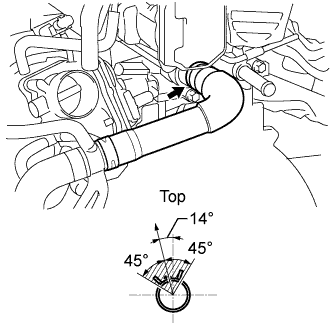
Connect the radiator hose to the cylinder head.
Tech Tips
The direction of the hose clamp is indicated in the illustration.
-
-
CONNECT CLUTCH HOSE (for Manual Transaxle)
-
Connect the clutch hose and install the clip to the clutch hose.
Note
Install the clip as far as it will go.
-
Using a 10 mm union nut wrench, connect the clutch hose to the flexible hose tube while holding the clutch hose.
- Torque:
- 15 N*m { 155 kgf*cm, 11 ft.*lbf }
Note
-
Use the formula to calculate special torque values for situations where a union nut wrench is combined with a torque wrench Click here.
-
Do not kink or damage the clutch hose.
-
Do not allow any foreign matter such as dirt or dust to enter the clutch hose from the clip or bracket.
-
This torque value is effective when the union nut wrench is parallel to the torque wrench.
-
-
CONNECT TRANSMISSION CONTROL CABLE ASSEMBLY (for Manual Transaxle)
-
Connect the control cable with the nut.
- Torque:
- 5.0 N*m { 51 kgf*cm, 44 in.*lbf }
-
Connect the 2 transmission control cables with 2 new clips.
-
Install the 2 clips.
-
-
CONNECT TRANSMISSION CONTROL CABLE ASSEMBLY (for CVT)
-
Connect the transmission control cable support together with the cable with the nut.
- Torque:
- 5.0 N*m { 51 kgf*cm, 44 in.*lbf }
-
Connect the transmission control cable to the control cable bracket.
-
Connect the transmission control cable to the bracket with a new clip.
-
Connect the transmission control cable to the control shaft lever with the nut.
- Torque:
- 12 N*m { 122 kgf*cm, 9 ft.*lbf }
-
-
INSTALL BATTERY CARRIER
-
Install the battery carrier with the 4 bolts.
- Torque:
- 19 N*m { 189 kgf*cm, 14 ft.*lbf }
-
Install the radiator pipe with the 2 bolts.
- Torque:
- 19 N*m { 189 kgf*cm, 14 ft.*lbf }
-
Connect the 2 wire harness clamps.
-
-
INSTALL BATTERY TRAY
-
INSTALL BATTERY
-
INSTALL BATTERY CLAMP SUB-ASSEMBLY
-
Install the battery clamp with the bolt and nut.
- Torque:
- for bolt
- 17 N*m { 168 kgf*cm, 12 ft.*lbf }
- for nut
- 3.5 N*m { 36 kgf*cm, 31 in.*lbf }
-
Connect the cable to the positive (+) battery terminal.
- Torque:
- 5.4 N*m { 55 kgf*cm, 48 in.*lbf }
-
-
INSTALL AIR CLEANER CASE SUB-ASSEMBLY
-
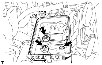
Install the air cleaner case with the 3 bolts.
- Torque:
- 7.0 N*m { 71 kgf*cm, 62 in.*lbf }
-
Attach the wire harness clamp to the air cleaner case.
-
-
INSTALL AIR CLEANER CAP SUB-ASSEMBLY
-
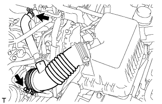
Connect the air cleaner cap with the band.
-
Connect the ventilation hose.
-
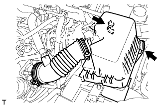
Connect the 2 clamps.
-
Attach the wire harness to the 2 clamps.
-
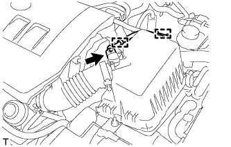
Connect the mass air flow meter connector.
-
-
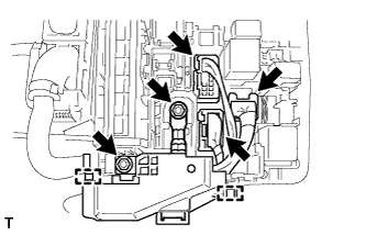
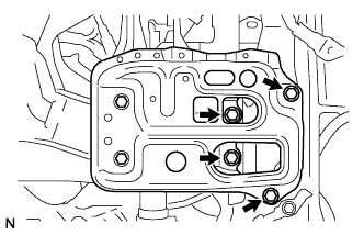
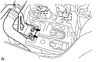
CONNECT COMPRESSOR WITH PULLEY ASSEMBLY (w/ Air Conditioning System)
-
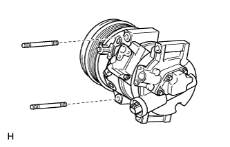
Using an E8 "TORX" socket wrench, connect the compressor with pulley assembly with the 2 stud bolts.
- Torque:
- 9.8 N*m { 100 kgf*cm, 87 in.*lbf }
-
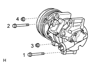
Install the 2 bolts and 2 nuts.
- Torque:
- 25 N*m { 255 kgf*cm, 18 ft.*lbf }
Tech Tips
Tighten the bolts and the nuts in the order shown in the illustration.
-
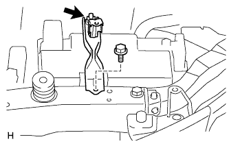
Connect the connector.
-
-
CONNECT NO. 2 RADIATOR HOSE
-
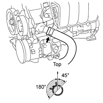
Connect the radiator hose to the water inlet.
Tech Tips
The direction of the hose clamp is indicated in the illustration.
-
-
INSTALL GENERATOR ASSEMBLY
-

Install the wire harness clamp bracket with the bolt.
- Torque:
- 8.4 N*m { 85 kgf*cm, 74 in.*lbf }
-
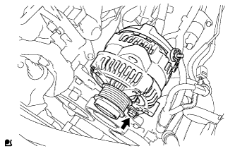
Temporarily install the generator with the bolt.
-
Temporarily install the adjusting bar with the 2 bolts.
-
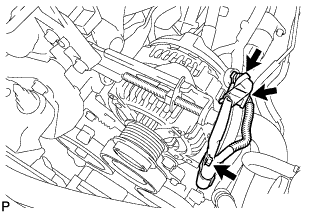
Install the wire harness to terminal B with the nut and install the terminal cap.
- Torque:
- 9.8 N*m { 100 kgf*cm, 87 in.*lbf }
-
Connect the connector and wire harness clamp.
-
Install the V-ribbed belt Click here.
-
Adjust the V-ribbed belt Click here.
-
Inspect the V-ribbed belt Click here.
-
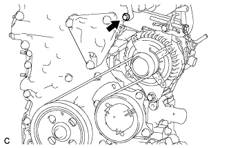
Tighten the bolt.
- Torque:
- 19 N*m { 189 kgf*cm, 14 ft.*lbf }
-
-
INSTALL V-RIBBED BELT
-
Temporarily install the V-ribbed belt.
-
-
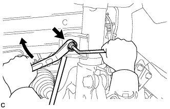
ADJUST V-RIBBED BELT
-
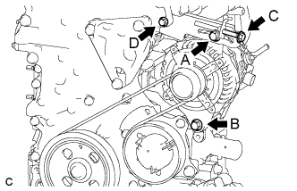
Turn bolt C to adjust the tension of the V-ribbed belt.
-
Tighten bolts A and B.
- Torque:
- for bolt A
- 19 N*m { 189 kgf*cm, 14 ft.*lbf }
- for bolt B
- 43 N*m { 438 kgf*cm, 32 ft.*lbf }
Note
Do not loosen bolt D.
-
-
CONNECT RADIATOR RESERVOIR ASSEMBLY
-
Install the grommet to the radiator reservoir.
-
Connect the radiator reservoir with the 2 bolts.
- Torque:
- 5.0 N*m { 51 kgf*cm, 44 in.*lbf }
-
-
CONNECT CABLE TO NEGATIVE BATTERY TERMINAL
Note
When disconnecting the cable, some systems need to be initialized after the cable is reconnected Click here.
-
ADD MANUAL TRANSAXLE OIL (for Manual Transaxle)
-

Add oil until the oil level is within 5 mm (0.197 in.) from the bottom of the transmission filler plug opening.
Manual Transaxle Gear Oil TOYOTA Genuine Manual Transmission Gear Oil LV or equivalent Oil Classification API GL-4 and SAE 75W Capacity 2.4 liters (2.5 US qts, 2.1 IMP. qts) -
Install a new gasket and the transmission filler plug.
- Torque:
- 39 N*m { 400 kgf*cm, 29 ft.*lbf }
Note
-
When adding transaxle oil, make sure the vehicle is level.
-
An excessively large or small amount of oil may cause problems.
-
After adding oil, drive the vehicle and recheck the oil level.
-
-
INSPECT MANUAL TRANSAXLE OIL (for Manual Transaxle)
-
Stop the vehicle on a level surface.
-
except Rough Road Area Specification Vehicles:
Remove the 8 clips and fold back the engine under cover.
Tech Tips
It is not necessary to fully remove the engine under cover. Partially remove it so that the oil level can be checked in a later step.
-
for Rough Road Area Specification Vehicles:
Remove the front lower bumper absorber Click here.
-
for Rough Road Area Specification Vehicles:
Remove the No. 1 engine under cover Click here.
-
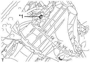
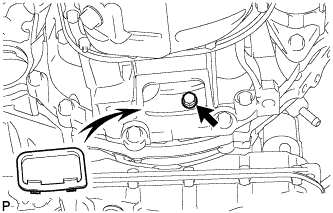
Text in Illustration *1 Filler Plug Remove the transmission filler plug and gasket.
-
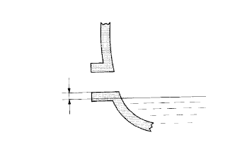
Check that the oil level is within 5 mm (0.187 in.) from the bottom of the transmission filler plug opening.
Note
An excessively large or small amount of oil may cause problems.
-
Check for oil leakage when the oil level is low.
-
Install a new gasket and the transmission filler plug.
- Torque:
- 39 N*m { 400 kgf*cm, 29 ft.*lbf }
-
for Rough Road Area Specification Vehicles:
Install the No. 1 engine under cover Click here.
-
for Rough Road Area Specification Vehicles:
Install the front lower bumper absorber Click here.
-
except Rough Road Area Specification Vehicles:
Install the engine under cover with the 8 clips.
-
-
ADD CONTINUOUSLY VARIABLE TRANSAXLE FLUID (for CVT)
-
Add continuously variable transaxle fluid Click here.
-
-
ADD ENGINE COOLANT
-
Tighten the radiator drain cock plug.
-
Tighten the cylinder block drain cock plug.
- Torque:
- 13 N*m { 130 kgf*cm, 9 ft.*lbf }
-
Add TOYOTA Super Long Life Coolant (SLLC) through the radiator reservoir filler opening until the coolant reaches the B line.
Standard Capacity Item Specified Condition for Manual transaxle 6.3 liters (6.7 US qts, 5.5 Imp. qts) for CVT 6.2 liters (6.6 US qts, 5.4 Imp. qts) Tech Tips
TOYOTA vehicles are filled with TOYOTA SLLC at the factory. In order to avoid damage to the engine cooling system and other technical problems, only use TOYOTA SLLC or similar high quality ethylene glycol based non-silicate, non-amine, non-nitrite, non-borate coolant with long-life hybrid organic acid technology (coolant with long-life hybrid organic acid technology is a combination of low phosphates and organic acids).
Note
Never use water as a substitute for engine coolant.
-
Squeeze the inlet and outlet radiator hoses several times by hand, and then check the level of the coolant.
If the coolant level is low, add coolant.
-
Install the cap and warm up the engine sufficiently.
-
Bleed air from the cooling system.
Note
-
Before starting the engine, turn the A/C switch off.
-
Adjust the air conditioning temperature setting to MAX (HOT).
-
Adjust the air conditioning blower setting to Lo.
-
Warm up the engine until the thermostat opens. While the thermostat is open, allow the coolant to circulate for several minutes.
Tech Tips
The thermostat opening timing can be confirmed by squeezing the inlet radiator hose by hand, and sensing vibrations when the engine coolant starts to flow inside the hose.
CAUTION:
When squeezing the radiator hose:
-
Wear protective gloves.
-
Be careful as the radiator hoses are hot.
-
Keep your hands away from the radiator fan.
-
-
After the engine has warmed up, repeat the following procedure for at least 7 minutes: run the engine at 3000 rpm for 5 seconds, and then at idle speed for 45 seconds (repeat this procedure at least 8 times).
-
Squeeze the inlet and outlet radiator hoses several times by hand to bleed air from the system.
CAUTION:
When squeezing the radiator hose:
-
Wear protective gloves.
-
Be careful as the radiator hoses are hot.
-
Keep your hands away from the radiator fan.
-
-
-
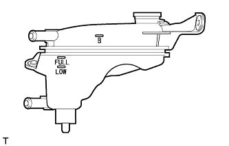
After the engine has cooled down, check that the coolant level is between FULL and LOW lines.
If the coolant level is low, add coolant to the FULL line on the reservoir.
-
-
ADD ENGINE OIL
-
Clean and install the oil pan drain plug together with a new gasket.
- Torque:
- 37 N*m { 377 kgf*cm, 27 ft.*lbf }
-
Add new engine oil.
Standard Oil Grade Oil Grade Oil Viscosity (SAE) API grade SL or SM multigrade engine oil
-
15W-40
-
20W-50
API grade SL "Energy-Conserving", SM "Energy-Conserving" or ILSAC multigrade engine oil
-
0W-20
-
5W-20
-
5W-30
-
10W-30
Standard Capacity Item Specified Condition Drain and refill without oil filter change 3.9 liters (4.1 US qts, 3.4 Imp. qts) Drain and refill with oil filter change 4.2 liters (4.4 US qts, 3.7 Imp. qts) Dry fill 4.7 liters (5.0 US qts, 4.1 Imp. qts) -
-
Install the oil filler cap.
-
-
INSPECT FOR FUEL LEAK
-
Make sure that there are no fuel leaks after performing maintenance on the fuel system.
-
Connect the intelligent tester to the DLC3.
-
Turn the ignition switch to ON, and push the intelligent tester main switch on.
Note
Do not start the engine.
-
Enter the following menus: Powertrain / Engine and ECT / Active Test / Control the Fuel Pump / Speed.
-
Check that there are no leaks from the fuel system.
-
Turn the ignition switch off.
-
Disconnect the intelligent tester from the DLC3.
-
-
-
INSPECT FOR COOLANT LEAK
CAUTION:
To avoid being burned, do not remove the reserve tank cap while the engine and radiator are still hot. Thermal expansion may cause hot engine coolant and steam to blow out from the radiator.
-
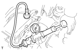
Fill the radiator with engine coolant, and then attach a radiator cap tester.
-
Warm up the engine.
-
Using the radiator cap tester, increase the pressure inside the radiator to 118 kPa (1.2 kgf/cm2, 17 psi), and then check that the pressure does not drop.
If the pressure drops, check the hoses, radiator and water pump for leakage. If there are no signs or traces of external engine coolant leakage, check the heater core, cylinder block and head.
-
-
INSPECT FOR OIL LEAK
-
Start the engine. Make sure that there are no oil leaks from the areas that were worked on.
-
-
INSPECT FOR EXHAUST GAS LEAK
If gas is leaking, tighten the areas necessary to stop the leak. Replace damaged parts as necessary.
-
INSPECT V-RIBBED BELT
-
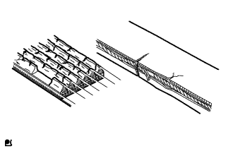
Check the belt for wear, cracks or other signs of damage.
If any of the following defects is found, replace the V-ribbed belt.
-
The belt is cracked.
-
The belt is worn out to the extent that the cords are exposed.
-
The belt has chunks missing from the ribs.
-
-
Check that the belt fits properly in the ribbed grooves.
Tech Tips
Check with your hand to confirm that the belt has not slipped out of the grooves on the bottom to the pulley. If it has slipped out, replace the V-ribbed belt. Install a new V-ribbed belt correctly.
-
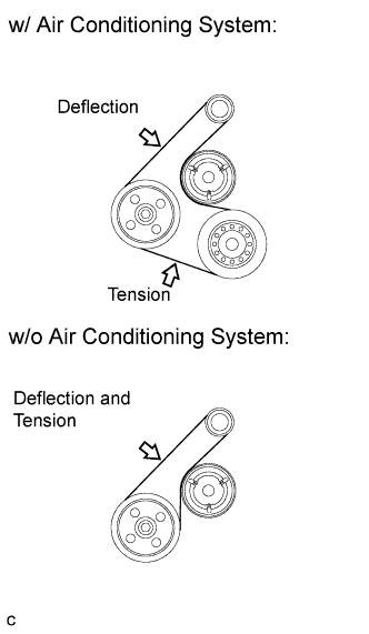
Check the V-ribbed belt deflection and tension.
Standard Deflection Item Specified Condition New belt 7.0 to 8.2 mm (0.276 to 0.323 in.) Used belt 7.6 to 10.0 mm (0.299 to 0.394 in.) Standard Tension Item Specified Condition New belt 700 to 800 N (70 to 80 kgf, 157.4 to 179.8 lbf) Used belt 550 to 750 N (55 to 75 kgf, 123.6 to 168.6 lbf) Tech Tips
-
When inspecting the V-ribbed belt deflection, apply 98 N (10 kgf, 22.0 lbf) of tensile force to it.
-
Check the V-ribbed belt deflection at the specified point.
-
V-ribbed belt tension and deflection should be checked after 2 revolutions of engine cranking.
-
Measure the belt tension when the engine is cold.
-
When adjusting the belt, be sure to adjust it so that the tension is as close as possible to the median of the specified range.
-
When replacing the belt with a new one, be sure to perform the following after adjusting the belt: idle the engine for 5 minutes, and then adjust the belt to the specified value for a new belt after the engine has cooled.
-
When inspecting a belt which has been used for over 5 minutes, apply the used belt specifications.
-
When using a belt tension gauge, confirm its accuracy by using a master gauge first.
-
-
-
INSPECT IGNITION TIMING
-
Warm up and stop the engine.
-
When using an intelligent tester:
-
Connect the intelligent tester to the DLC3.
-
Start the engine and idle it.
-
Turn the intelligent tester main switch on.
-
Enter the following menus: Powertrain / Engine and ECT / Data List / IGN Advance.
Standard ignition timing 8 to 12° BTDC @ idle Tech Tips
Refer to the intelligent tester operator's manual for further details.
Note
-
Turn all the electrical systems and the A/C off.
-
Check the ignition timing with the cooling fan off.
-
When checking the ignition timing, the shift lever should be in neutral or P (for CVT).
-
-
-
When not using the intelligent tester:
-
Remove the No. 2 cylinder head cover.
-
Connect the tester probe of a timing light to the wire of the ignition coil connector for the No. 1 cylinder.
Note
Use a timing light that detects primary signals.
-
Start the engine and idle it.
-
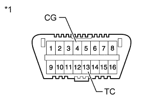
Text in Illustration *1 Front view of DLC3 Using SST, connect terminals 13 (TC) and 4 (CG) of the DLC3.
- SST
- 09843-18040
Note
-
Confirm the terminal numbers before connecting them. Connecting the wrong terminals can damage the engine.
-
When checking the ignition timing, the shift lever should be in neutral or P (for CVT).
-
Using the timing light, check the ignition timing.
Standard ignition timing 8 to 12° BTDC @ idle Note
-
Turn all the electrical systems and the A/C off.
-
Check the ignition timing with the cooling fan off.
-
When checking the ignition timing, the shift lever should be in neutral or P (for CVT).
-
-
Remove SST from the DLC3.
-
Check that the ignition timing advances immediately when the engine speed is increased.
-
Turn the ignition switch off.
-
Remove the timing light.
-
Install the No. 2 cylinder head cover.
-
-
-
INSPECT ENGINE IDLE SPEED
-
Warm up and stop the engine.
-
When using the intelligent tester:
-
Connect the intelligent tester to the DLC3.
-
Turn the ignition switch to ON.
-
Enter the following menus: Powertrain / Engine and ECT / Data List / Engine Speed.
Standard Idle Speed Item Specified Condition for Manual Transaxle 580 to 680 rpm for CVT 600 to 700 rpm Tech Tips
Refer to the intelligent tester operator's manual for further details.
Note
-
Turn all the electrical systems and the A/C off.
-
Check the ignition timing with the cooling fan off.
-
When checking the idling speed, the shift lever should be in neutral or P (for CVT).
-
-
-
Turn the ignition switch off.
-
Disconnect the intelligent tester from the DLC3.
-
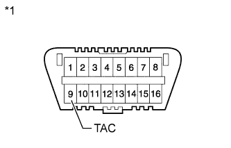
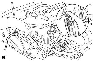
Text in Illustration *1 Front view of DLC3 When not using the intelligent tester:
-
Using SST, connect a tachometer probe to terminal 9 (TAC) of the DLC3.
- SST
- 09843-18030
Note
-
Confirm the terminal numbers before connecting them. Connecting the wrong terminals can damage the engine.
-
When checking the idling speed, the shift lever should be in neutral or P (for CVT).
-
Check the idle speed.
Standard Idle Speed Item Specified Condition for Manual Transaxle 580 to 680 rpm for CVT 600 to 700 rpm -
Disconnect the tachometer probe from the DLC3.
-
-
-
INSPECT CO/HC
-
Start the engine.
-
Run the engine at 2500 rpm for approximately 180 seconds.
-
Insert the CO/HC meter testing probe at least 40 cm (1.31 ft.) into the tailpipe while idling.
-
Check the CO/HC concentration during idling and when the engine is running at 2500 rpm.
Tech Tips
When doing the 2 mode (with the engine idling/ running at 2500 rpm) test, the measuring procedures are determined by applicable local regulations.
If the CO/HC concentration does not comply with the regulations, troubleshoot in the order given below.
-
Check the air fuel ratio sensor Click here and heated oxygen sensor operation Click here.
-
See the table below for possible causes, and then inspect the applicable parts and repair them if necessary.
CO HC Problems Possible Causes Normal High Rough idling
-
Faulty ignition:
-
Incorrect timing
-
Plugs are contaminated or shorted, or gaps are defective
-
Incorrect valve clearance
-
Leakage from intake or exhaust valves
-
Leakage from cylinders
Low High Rough idling
(Fluctuating HC reading)
-
Vacuum leaks:
-
PCV hoses
-
Intake manifold
-
Throttle body
-
Brake booster line
-
Lean mixture causing misfire
High High Rough idling
(Black smoke from exhaust)
-
Restricted air cleaner filter element
-
Plugged PCV valve
-
Faulty SFI system:
-
Faulty pressure regulator
-
Faulty engine coolant temperature sensor
-
Faulty mass air flow meter
-
Faulty ECM
-
Faulty injectors
-
Faulty throttle body
-
-
-
-
INSTALL FRONT WHEEL
- Torque:
- 103 N*m { 1050 kgf*cm, 76 ft.*lbf }
-
ADJUST FRONT WHEEL ALIGNMENT
-
Adjust the front wheel alignment Click here.
-
-
PERFORM CLUTCH ENGAGEMENT POINT LEARNING (for Manual Transaxle)
-
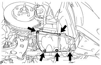
INSTALL NO. 2 ENGINE UNDER COVER
-
Install the under cover with the 4 clips.
-
-
INSTALL CENTER NO. 4 ENGINE UNDER COVER
-
Install the under cover with the 2 clips.
-
-
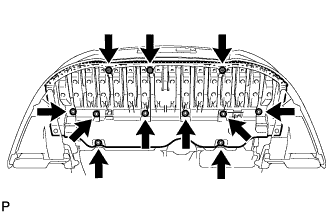
INSTALL REAR ENGINE UNDER COVER RH
-
Install the under cover RH with the 5 clips.
-
-
INSTALL REAR ENGINE UNDER COVER LH
-
Install the under cover LH with the 5 clips.
-
-
INSTALL NO. 1 ENGINE UNDER COVER
-
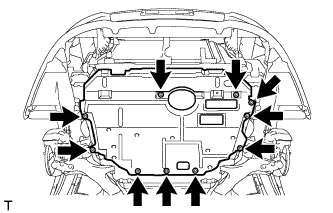
Install the under cover with the 10 clips.
-
-
INSTALL FRONT LOWER BUMPER ABSORBER
-
Install the front lower bumper absorber with the 3 screws and 8 bolts.
-
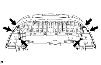
Install the 4 screws and 2 bolts.
-
-
INSTALL RADIATOR SUPPORT OPENING COVER
-
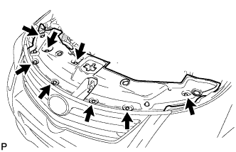
Install the radiator support opening cover with the 8 clips.
-
-
INSTALL ENGINE ROOM SIDE COVER
-

Install the engine room side cover with the clip.
-
-
INSTALL NO. 2 CYLINDER HEAD COVER
-
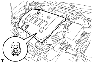
Attach the 4 clips to install the cover.
Note
-
Be sure to attach the clips securely.
-
Do not apply excessive force or hit the cover to attach the clips. This may cause the cover to break.
-
-