ENGINE ASSEMBLY REMOVAL

Note
for Manual Transaxle:
When the transaxle is removed, be sure to use a new clutch release with bearing cylinder and new installation bolts. Removal of the transaxle allows the compressed clutch release with bearing cylinder to return to its original position, and dust could damage the seal of the clutch release with bearing cylinder, possibly causing clutch fluid leaks.
-
INSPECT DRIVE AWAY RELEASE FUNCTION (for Manual Transaxle)
-
DISCHARGE FUEL SYSTEM PRESSURE
-
Discharge fuel system pressure Click here.
-
-
REMOVE NO. 2 CYLINDER HEAD COVER
-
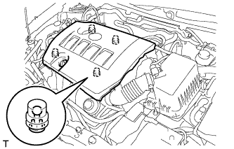
Hold the rear of the cover and raise it to detach the 2 clips on the rear of the cover. Continue to raise the cover to detach the 2 clips on the front of the cover and remove the cover.
Note
Attempting to detach both front and rear clips at the same time may cause the cover to break.
-
-
REMOVE RADIATOR SUPPORT OPENING COVER
-
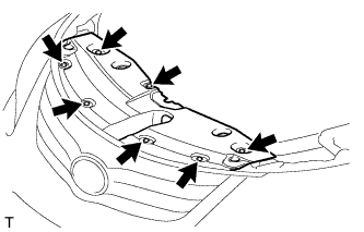
Remove the 7 clips and radiator support opening cover.
-
-
PRECAUTION
Note
After turning the ignition switch off, waiting time may be required before disconnecting the cable from the battery terminal. Therefore, make sure to read the disconnecting the cable from the battery terminal notice before proceeding with work Click here.
-
DISCONNECT CABLE FROM NEGATIVE BATTERY TERMINAL
Note
When disconnecting the cable, some systems need to be initialized after the cable is reconnected Click here.
-
ALIGN FRONT WHEELS FACING STRAIGHT AHEAD
-
REMOVE FRONT WHEEL
-
REMOVE FRONT LOWER BUMPER ABSORBER
-
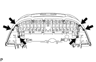
Remove the 4 screws and 2 bolts.
-
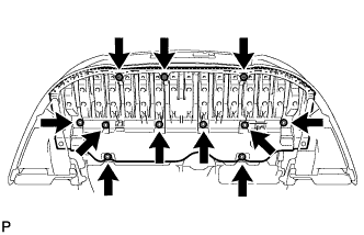
Remove the 3 screws, 8 bolts and front lower bumper absorber.
-
-
REMOVE NO. 1 ENGINE UNDER COVER
-
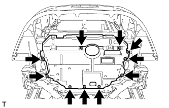
Remove the 10 clips and under cover.
-
-
REMOVE NO. 1 ENGINE UNDER COVER (for Rough Road Area Specification Vehicles)
-
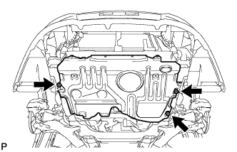
Remove the 3 clips and under cover.
-
-
REMOVE REAR ENGINE UNDER COVER RH
-
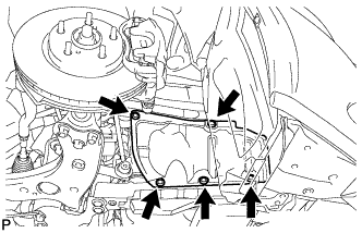
Remove the 5 clips and under cover RH.
-
-
REMOVE REAR ENGINE UNDER COVER LH
-
Remove the 5 clips and under cover.
-
-
REMOVE CENTER NO. 4 ENGINE UNDER COVER
-
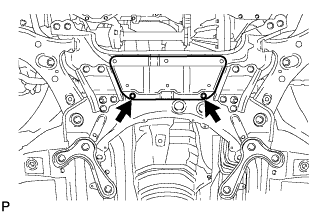
Remove the 2 clips and under cover.
-
-
REMOVE NO. 2 ENGINE UNDER COVER
-
Remove the 4 clips and under cover.
-
-
DRAIN ENGINE COOLANT
-
Loosen the radiator drain cock plug.
Tech Tips
Collect the coolant in a container and dispose of it according to the regulations in your area.
-
Remove the reserve tank cap.
CAUTION:
Do not remove the reserve tank cap while the engine and radiator are still hot.
Pressurized, hot engine coolant and steam may be released and cause serious burns.
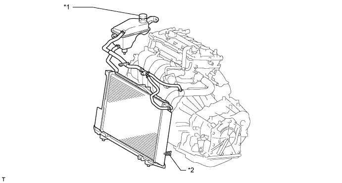
Text in Illustration *1 Reserve Tank Cap *2 Radiator Drain Cock Plug
-
-
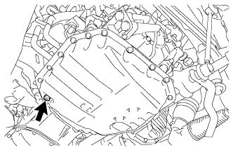
DRAIN ENGINE OIL
-
Remove the oil filler cap.
-
Remove the 3 clips and open the oil pan drain service cover.
-
Remove the oil pan drain plug and gasket, and drain the engine oil into a container.
-
-
DRAIN MANUAL TRANSAXLE OIL (for Manual Transaxle)
-
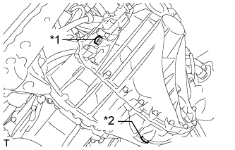
Text in Illustration *1 Filler Plug *2 Drain Plug Remove the filler plug and gasket.
-
Remove the drain plug and gasket to drain the manual transaxle oil.
-
Install a new gasket and the drain plug.
- Torque:
- 39 N*m { 400 kgf*cm, 29 ft.*lbf }
-
-
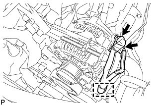
DRAIN CONTINUOUSLY VARIABLE TRANSAXLE FLUID (for CVT)
-
Using a 6 mm socket hexagon wrench, remove the overflow plug and gasket from the continuously variable transaxle assembly.
-
Text in Illustration *1 No. 1 Transmission Oil Filler Tube Using a 6 mm socket hexagon wrench, remove the No. 1 transmission oil filler tube from the continuously variable transaxle assembly and drain the continuously variable transaxle fluid.
-
Using a 6 mm socket hexagon wrench, install the No. 1 transmission oil filler tube to the continuously variable transaxle assembly.
- Torque:
- 1.7 N*m { 17 kgf*cm, 15 in.*lbf }
-
Temporarily install the gasket and overflow plug.
Tech Tips
Reuse the old gasket. The plug will be removed again to adjust the fluid level.
-
-
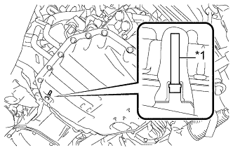
DISCONNECT RADIATOR RESERVOIR ASSEMBLY
-
Remove the 2 bolts and disconnect the radiator reservoir.
-
Remove the grommet from the radiator reservoir.
-
-
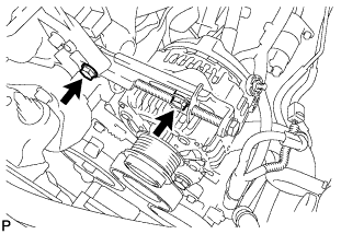
REMOVE V-RIBBED BELT
-
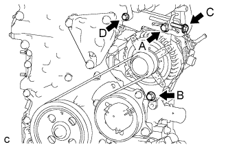
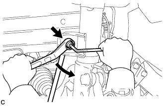
Loosen bolts A and B.
-
Loosen bolt C and remove the V-ribbed belt.
Note
Do not loosen bolt D.
-
-
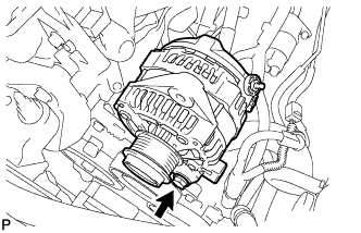
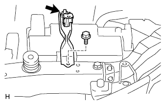
REMOVE GENERATOR ASSEMBLY
-
Remove the terminal cap.
-
Remove the nut and disconnect the wire harness from terminal B.
-
Disconnect the connector and detach the wire harness clamp.
-
Remove the 2 bolts and adjusting bar.
-
Remove the bolt and generator.
-
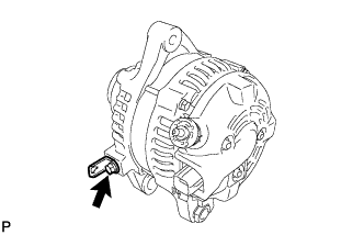
Remove the bolt and wire harness clamp bracket.
-
-
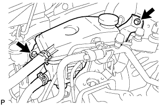
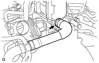
DISCONNECT NO. 2 RADIATOR HOSE
-
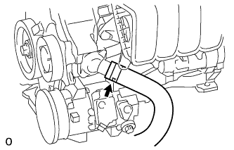
Disconnect the radiator hose from the water inlet.
-
-
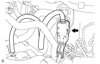
DISCONNECT COMPRESSOR WITH PULLEY ASSEMBLY (w/ Air Conditioning System)
-
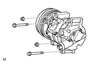
Disconnect the connector.
-
Remove the 2 bolts and 2 nuts.
-
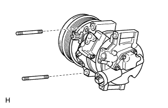
Using an E8 "TORX" socket wrench, remove the 2 stud bolts and disconnect the compressor assembly with pulley.
Tech Tips
It is not necessary to completely remove the compressor. With the hoses connected to the compressor, hang the compressor on the vehicle body with a rope.
-
-
REMOVE AIR CLEANER CAP SUB-ASSEMBLY
-
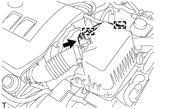
Disconnect the mass air flow meter connector.
-
Detach the wire harness from the 2 clamps.
-
Disconnect the 2 clamps.
-
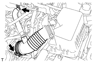
Disconnect the ventilation hose.
-
Loosen the band and remove the air cleaner cap.
-
-
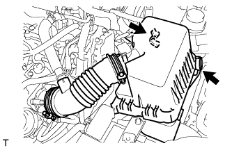
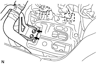
REMOVE AIR CLEANER CASE SUB-ASSEMBLY
-
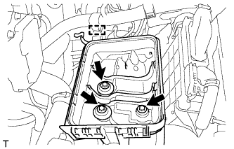
Detach the wire harness clamp from the air cleaner case.
-
Remove the 3 bolts and air cleaner case.
-
-
REMOVE BATTERY CLAMP SUB-ASSEMBLY
-
Disconnect the cable from the positive (+) battery terminal.
-
Remove the bolt and loosen the nut.
-
Remove the battery clamp.
-
-
REMOVE BATTERY
-
REMOVE BATTERY TRAY
-
REMOVE BATTERY CARRIER
-
Disconnect the 2 wire harness clamps from the battery carrier.
-
Remove the 2 bolts and disconnect the radiator pipe from the battery carrier.
-
Remove the 4 bolts and battery carrier.
-
-
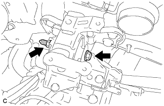
DISCONNECT TRANSMISSION CONTROL CABLE ASSEMBLY (for Manual Transaxle)
-
Remove the 2 clips and disconnect the 2 cables from the transaxle.
-
Remove the 2 clips and disconnect the 2 control cables from the control cable bracket.
-
Remove the nut and disconnect the control cable.
-
-
DISCONNECT TRANSMISSION CONTROL CABLE ASSEMBLY (for CVT)
-
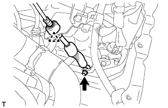
Remove the nut and disconnect the control cable from the control shaft lever.
-
Remove the clip and disconnect the transmission control cable from the control cable bracket.
-
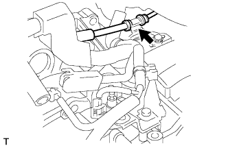
Disconnect the control cable from the control cable bracket.
-
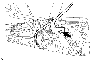
Remove the nut and disconnect the transmission control cable support together with the cable.
-
-
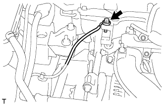
DISCONNECT CLUTCH HOSE (for Manual Transaxle)
-
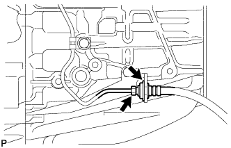
Using a 10 mm union nut wrench, disconnect the clutch hose from the flexible hose tube.
-
Remove the clip and disconnect the clutch hose.
-
-
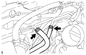
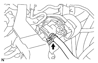
DISCONNECT NO. 1 RADIATOR HOSE
-
Disconnect the radiator hose from the cylinder head.
-
-
DISCONNECT FUEL TUBE SUB-ASSEMBLY
-
Release the claw and remove the No. 1 fuel pipe clamp.
-
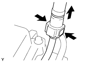
Pinch the retainer as illustrated, and then pull the fuel tube connector off of the pipe.
Note
-
Remove any dirt and foreign matter from the fuel tube connector before performing this step.
-
Do not allow any scratches or foreign matter on the parts when disconnecting the fuel tube connector, as the connector contains the O-rings that seal the pipe.
-
Perform this work by hand. Do not use any tools.
-
Do not forcibly bend, kink or twist the nylon tube.
-
Protect the disconnected parts by covering them with plastic bags after disconnecting the fuel tube.
-
If the fuel tube connector and pipe are stuck, push and pull to release them.
-
-
-
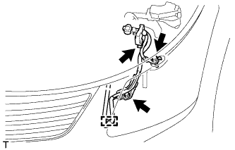
DISCONNECT HEATER WATER HOSE
-
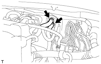
Disconnect the 2 heater water hoses.
-
-
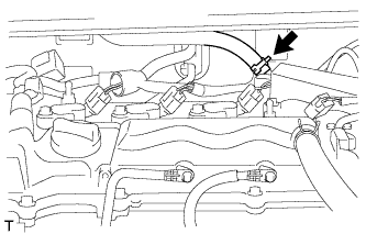
DISCONNECT WIRE HARNESS AND HOSE
-
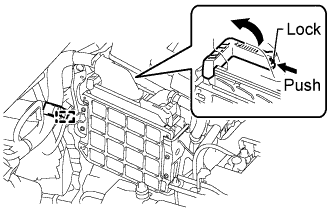
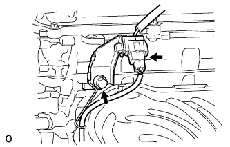
Disconnect the clamp and ECM connector.
-
Raise the lever while pushing the locks on the levers, and disconnect the ECM connector.
Note
After disconnecting the connector, make sure that dirt, water or other foreign matter does not contact the connecting parts of the connector.
-
-
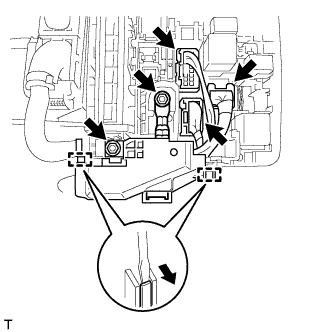
Remove the 2 nuts from the engine room No 1 relay block.
-
Disconnect the 3 connectors, detach the 2 clamps from the engine room No. 1 relay block and disconnect the wire harness.
-
Disconnect the connector from the battery current sensor.
-
Remove the 2 bolts and disconnect the clamp and engine wire.
-
for CVT:
Disconnect the 2 oil cooler hoses from the oil cooler tube.
-
Remove the bolt and disconnect the engine wire.
-
Disconnect the connector tube hose.
-
Disconnect the vacuum hose.
-
-
SECURE STEERING WHEEL ASSEMBLY
-
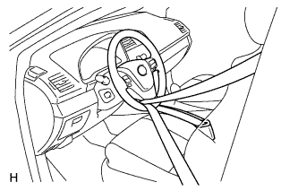
Secure the steering wheel with the seat belt in order to prevent rotation.
Tech Tips
This operation is useful to prevent damage to the spiral cable.
-
-
REMOVE COLUMN HOLE COVER SILENCER SHEET
-
Fold back the floor carpet, and then remove the 2 clips and then column hole cover silencer sheet.
-
-
DISCONNECT NO. 2 STEERING INTERMEDIATE SHAFT ASSEMBLY
-
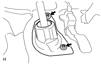
Remove the bolt.
Note
Do not disconnect the No. 2 steering intermediate shaft assembly from the steering intermediate shaft.
-
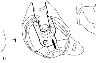
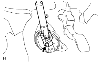
Text in Illustration *1 Matchmark Put matchmarks on the No. 2 steering intermediate shaft assembly and steering intermediate shaft.
-
Disconnect the No. 2 steering intermediate shaft assembly from the steering intermediate shaft.
-
-
DISCONNECT NO. 1 STEERING COLUMN HOLE COVER SUB-ASSEMBLY
-
Remove the No. 1 steering column hole cover from the steering link.
-
-
REMOVE FRONT CENTER FLOOR BRACE
-
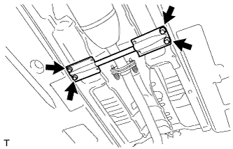
Remove the 4 bolts and floor brace.
-
-
REMOVE FRONT EXHAUST PIPE ASSEMBLY
-
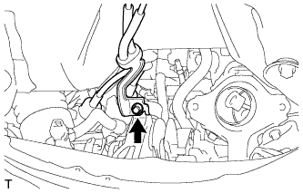
Detach the clamp and disconnect the heated oxygen sensor wire harness.
-
Disconnect the heated oxygen sensor connector.
-
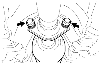
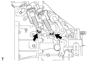
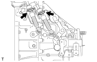
Remove the 2 bolts and 2 compression springs.
-
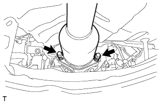
Remove the 2 bolts and 2 compression springs.
-
Remove the 2 exhaust pipe supports and front exhaust pipe assembly.
-
-
REMOVE FRONT AXLE SHAFT NUT LH
-
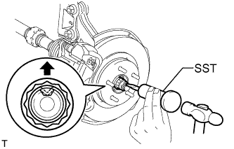
Using SST and a hammer, unstake the staked part of the front axle shaft nut.
- SST
- 09930-00010
Note
Loosen the staked part of the front axle shaft nut completely, otherwise the screw of the drive shaft may be damaged.
-
While applying the brakes, remove the front axle shaft nut.
-
-
REMOVE FRONT AXLE SHAFT NUT RH
Tech Tips
Perform the same procedures described for the LH side.
-
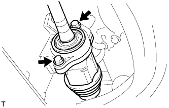
DISCONNECT FRONT STABILIZER LINK ASSEMBLY LH
-
Remove the nut and disconnect the stabilizer link assembly from the front shock absorber with coil spring.
Tech Tips
If the ball joint turns together with the nut, use a 6 mm hexagon wrench to hold the stud bolt.
-
-
DISCONNECT FRONT STABILIZER LINK ASSEMBLY RH
Tech Tips
Perform the same procedures described for the LH side.
-
REMOVE FRONT AXLE ASSEMBLY LH
-
Remove the front axle assembly LH Click here.
-
-
REMOVE FRONT AXLE ASSEMBLY RH
Tech Tips
Perform the same procedures described for the LH side.
-
REMOVE FRONT DRIVE SHAFT ASSEMBLY LH
-
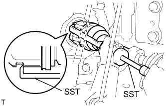
Using SST, remove the front drive shaft.
- SST
- 09520-00031
- 09520-01010
Note
-
Be careful not to damage the transaxle case oil seal, inboard joint boot or drive shaft dust cover.
-
Be careful not to drop the drive shaft.
-
-
REMOVE FRONT DRIVE SHAFT ASSEMBLY RH
-
Remove the 2 bolts and pull out the drive shaft together with the drive shaft bearing case from the transaxle.
Note
-
Be careful not to damage the inboard joint boot or drive shaft dust cover.
-
Be careful not to drop the drive shaft.
-
-
-
REMOVE DRIVE PLATE AND TORQUE CONVERTER SETTING BOLT (for CVT)
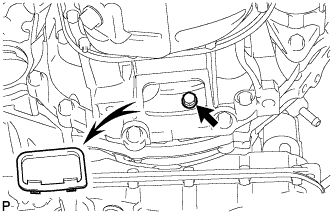
-
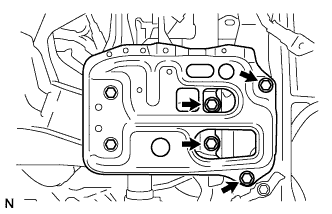
Remove the flywheel housing under cover.
-
Turn the crankshaft to gain access to the 6 bolts and remove each bolt while holding the crankshaft pulley bolt with a wrench.
Tech Tips
There is one black colored bolt.
-
-
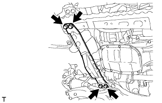
REMOVE FRONT SUSPENSION MEMBER REINFORCEMENT LH
-
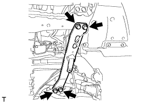
Remove the 4 bolts and front suspension member reinforcement LH.
-
-
REMOVE FRONT SUSPENSION MEMBER REINFORCEMENT RH
-
Remove the 4 bolts and front suspension member reinforcement RH.
-
-
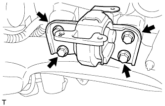
REMOVE FRONT CROSSMEMBER SUB-ASSEMBLY
-
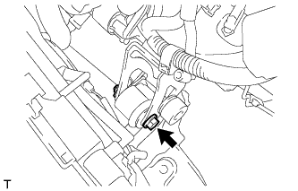
Remove the bolt and nut.
Tech Tips
While holding the nut in place, loosen the bolt.
-
Remove the front engine mounting insulator from the front engine mounting bracket.
-
Remove the 4 bolts and front crossmember.
-
-
REMOVE ENGINE ASSEMBLY WITH TRANSAXLE
-
Set an engine lifter underneath the engine.
Note
Place the engine on wooden blocks or equivalent so that the engine is level.
-
Remove the bolt and 2 nuts, and disconnect the engine mounting insulator RH.
-
Remove the bolt and nut, and disconnect the engine mounting insulator LH.
-
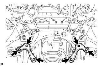
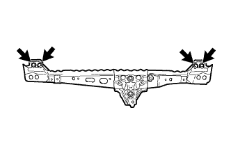
Remove the 6 bolts and front suspension member brace rear RH and LH.
-
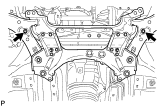
Remove the 2 bolts and front suspension crossmember.
-
Operate the engine lifter and slowly remove the engine from the vehicle.
Note
-
Make sure that the engine is clear of all wiring and hoses.
-
While lowering the engine from the vehicle, do not allow it to contact the vehicle.
-
-
-
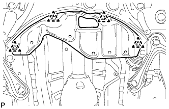
INSTALL ENGINE HANGER
-
Disconnect the air fuel ratio sensor connector and remove the bolt and air fuel ratio sensor bracket.
-
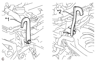
Text in Illustration *1 No. 1 Engine Hanger *2 No. 2 Engine Hanger Install the 2 engine hangers with 2 bolts as shown in the illustration.
- Torque:
- 43 N*m { 438 kgf*cm, 32 ft.*lbf }
Tech Tips
No. 1 Engine Hanger 12281-37021 No. 2 Engine Hanger 12282-37011 Bolt 91552-81050 -
Attach an engine sling device and hang the engine with a chain block.
-
-
REMOVE FRONT SUSPENSION CROSSMEMBER SUB-ASSEMBLY
-
Remove the bolt and front suspension crossmember from the engine.
-
-
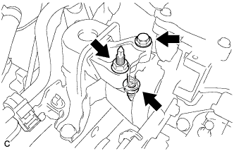
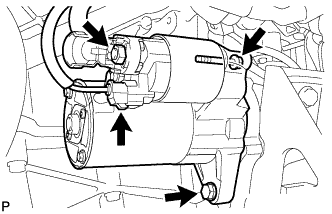
REMOVE STARTER ASSEMBLY
-
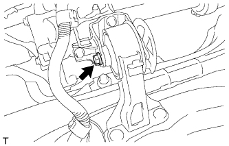
Disconnect the terminal cap.
-
Remove the nut and disconnect the starter wire.
-
Disconnect the connector.
-
Remove the 2 bolts and starter.
-
-
REMOVE FLYWHEEL HOUSING SIDE COVER
-
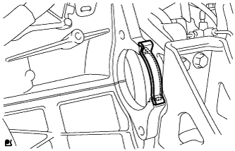
Remove the flywheel housing side cover from the cylinder block.
-
-
REMOVE MANUAL TRANSAXLE ASSEMBLY (for Manual Transaxle)
-
Remove the manual transaxle assembly Click here.
-
-
REMOVE CONTINUOUSLY VARIABLE TRANSAXLE ASSEMBLY (for CVT)
-
Remove the continuously variable transaxle assembly Click here.
-
-
REMOVE CLUTCH COVER ASSEMBLY (for Manual Transaxle)
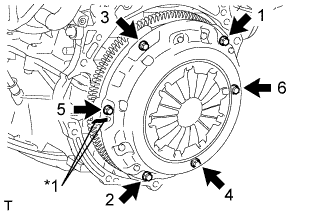
Text in Illustration *1 Matchmark
-
Put matchmarks on the clutch cover assembly and flywheel sub-assembly.
-
Loosen each set bolt one turn at a time in the order shown in the illustration until the spring tension is released.
-
Remove the set bolts and pull off the clutch cover assembly.
Note
Do not drop the clutch disc assembly.
-
-
REMOVE CLUTCH DISC ASSEMBLY (for Manual Transaxle)
-
REMOVE CLUTCH RELEASE WITH BEARING CYLINDER ASSEMBLY (for Manual Transaxle)
-
Remove the clutch release with bearing cylinder assembly Click here.
-
-
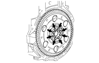
REMOVE FLYWHEEL SUB-ASSEMBLY (for Manual Transaxle)
-
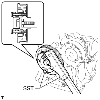
Using SST, hold the crankshaft.
- SST
- 09330-00021
- 09213-58014 ( 91551-80840 )
-
Remove the 8 bolts and flywheel.
-
-
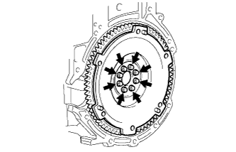
REMOVE DRIVE PLATE AND RING GEAR SUB-ASSEMBLY (for CVT)
-
Using SST, hold the crankshaft.
- SST
- 09330-00021
- 09213-58014 ( 91551-80840 )
-
Remove the 8 bolts, rear spacer, drive plate and front spacer.
-
-
REMOVE ENGINE WIRE
-
Remove the engine wire from the engine.
-
-
INSTALL ENGINE ON ENGINE STAND
-
Install the engine onto an engine stand with the bolts.
-
Remove the 2 bolts and 2 engine hangers.
-
-
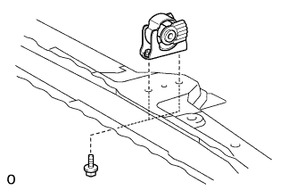
REMOVE FRONT ENGINE MOUNTING INSULATOR
Tech Tips
Perform this procedure only when replacement of the engine mounting insulator is necessary.
-
Remove the 2 bolts and front engine mounting insulator.
-
-
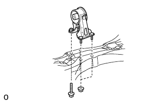
REMOVE REAR ENGINE MOUNTING INSULATOR
Tech Tips
Perform this procedure only when replacement of the engine mounting insulator is necessary.
-
Remove the 2 bolts, 2 nuts and engine mounting insulator.
-
-
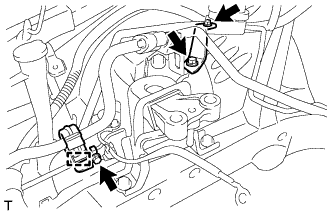
REMOVE ENGINE MOUNTING INSULATOR SUB-ASSEMBLY RH
Tech Tips
Perform this procedure only when replacement of the engine mounting insulator is necessary.
-
Disconnect the cooler pipe clamp.
-
Remove the 2 bolts, nut and 2 cooler pipe brackets.
-
Remove the 3 bolts and engine mounting insulator.
-
-
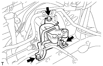
REMOVE ENGINE MOUNTING INSULATOR SUB-ASSEMBLY LH
Tech Tips
Perform this procedure only when replacement of the engine mounting insulator is necessary.
-
Remove the 4 bolts and engine mounting insulator.
-