OUTER REAR VIEW MIRROR REMOVAL
Tech Tips
-
Use the same procedure for both the RH and LH sides.
-
The procedure described below is for the LH side.
-
PRECAUTION
Note
After turning the power switch off, waiting time may be required before disconnecting the cable from the auxiliary battery negative (-) terminal. Therefore, make sure to read the disconnecting the cable from the auxiliary battery negative (-) terminal notices before proceeding with work Click here.
-
REMOVE REAR NO. 3 FLOOR BOARD
-
Remove the rear No. 3 floor board.
-
-
REMOVE DECK FLOOR BOX RH
-
Fold back the rear No. 2 floor board.
-
Remove the deck floor box RH Click here.
-
-
REMOVE REAR NO. 3 FLOOR BOARD UPPER PLATE
-
Disengage the 2 claws and remove the rear No. 3 floor board upper plate.
-
-
DISCONNECT CABLE FROM NEGATIVE AUXILIARY BATTERY TERMINAL
Note
When disconnecting the cable, some systems need to be initialized after the cable is reconnected Click here.
-
REMOVE FRONT DOOR INSIDE HANDLE BEZEL PLUG
-
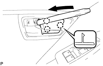
Using a moulding remover, disengage the 3 claws and remove the front door inside handle bezel plug.
-
-
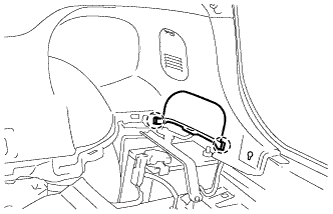
REMOVE ASSIST GRIP COVER
-
Using a moulding remover, disengage the 6 claws, 2 clips and 3 guides, and remove the assist grip cover.
-
-
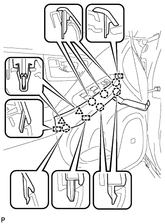
REMOVE POWER WINDOW REGULATOR MASTER SWITCH ASSEMBLY WITH FRONT DOOR ARMREST BASE PANEL (for Driver Side)
-
Disengage the 7 claws and 3 guides.
-
Disconnect the connector and remove the power window regulator master switch assembly with front door armrest base panel.
-
-
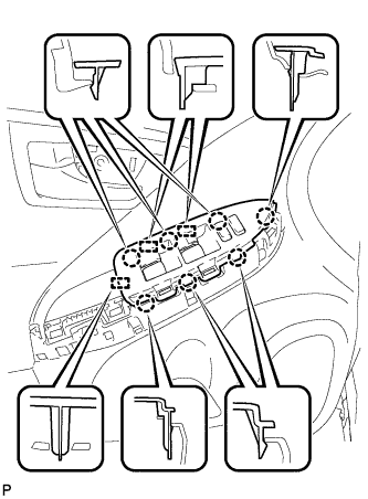
REMOVE POWER WINDOW REGULATOR SWITCH ASSEMBLY WITH FRONT DOOR ARMREST BASE PANEL (for Front Passenger Side)
-
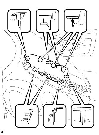
Disengage the 7 claws and 3 guides.
-
Disconnect each connector and remove the power window regulator switch assembly with front door armrest base panel.
-
-
REMOVE DOOR ARMREST COVER
-
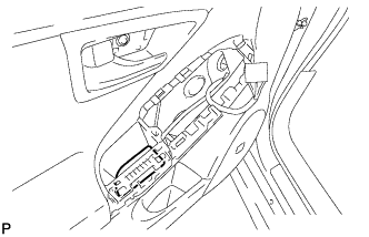
Remove the door armrest cover.
-
-
REMOVE COURTESY LIGHT ASSEMBLY
-
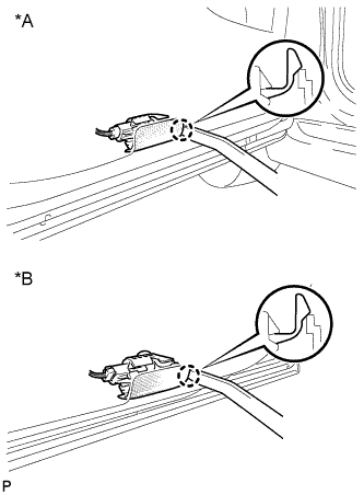
Text in Illustration *A for LH Side *B for RH Side Using a moulding remover, disengage the claw.
-
Disconnect the connector and remove the courtesy light assembly.
-
-
REMOVE FRONT DOOR TRIM BOARD SUB-ASSEMBLY
-
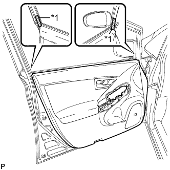
Text in Illustration *1 Protective Tape Put protective tape around the front door panel.
-
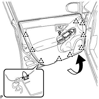
Remove the 2 screws.
-
Using a clip remover, disengage the 9 clips.
-
Pull out the front door trim board sub-assembly in the direction indicated by the arrow in the illustration.
-
Raise the front door trim board sub-assembly and remove the front door trim board sub-assembly together with the front door inner glass weatherstrip.
-
Disengage the 2 claws and disconnect the front door inside handle sub-assembly.
-
-
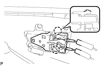
REMOVE FRONT DOOR INSIDE HANDLE SUB-ASSEMBLY
-
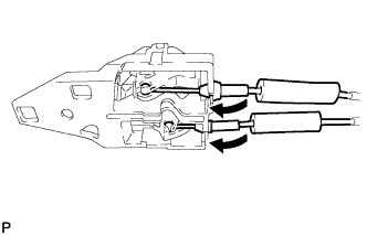
Disconnect the front door lock remote control cable and front door inside locking cable, and remove the front door inside handle sub-assembly.
-
-
REMOVE OUTER MIRROR PROTECTOR
-
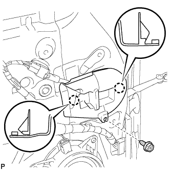
Remove the screw.
-
Disengage the 2 claws and remove the outer mirror protector.
-
-
REMOVE OUTER MIRROR INSTALL HOLE COVER
-
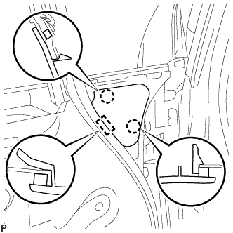
Disengage the 2 claws and guide, remove the outer mirror install hole cover.
-
-
REMOVE OUTER REAR VIEW MIRROR ASSEMBLY
-
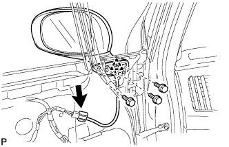
Disconnect the connector.
-
Remove the 3 bolts.
-
Disengage the clip and remove the outer rear view mirror assembly.
-
-
REMOVE OUTER MIRROR
-
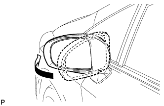
Push the outside part of the outer rear view mirror assembly and tilt it as show in the illustration.
-
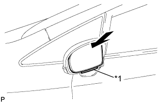
Text in Illustration *1 Protective Tape Push the upper part of the outer mirror surface and tilt it.
-
Apply protective tape as shown in the illustration.
-
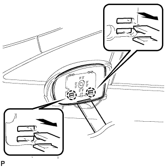
Using a moulding remover, disengage the 2 claws at the lower part of the outer mirror, and separate the outer mirror.
Note
Do not pull the outer mirror with excessive force. Doing so may cause the actuator to come off or break the outer mirror surface.
-
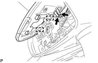
Disengage the 2 guides as shown in the illustration.
-
Disconnect the 2 connectors and remove the outer mirror.
-
-
REMOVE OUTER MIRROR COVER
-
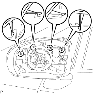
Disengage the 4 claws.
-
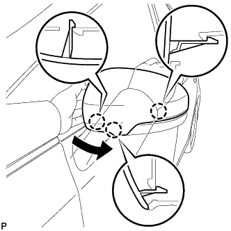
Disengage the 3 claws and remove the outer mirror cover as shown in the illustration.
-