REAR DOOR DISASSEMBLY
Tech Tips
-
Use the same procedure for both the RH and LH sides.
-
The procedure described below is for the LH side.
-
PRECAUTION
Note
After turning the power switch off, waiting time may be required before disconnecting the cable from the negative (-) auxiliary battery terminal. Therefore, make sure to read the disconnecting the cable from the negative (-) auxiliary battery terminal notices before proceeding with work Click here.
-
REMOVE REAR NO. 3 FLOOR BOARD
-
Remove the rear No. 3 floor board.
-
-
REMOVE DECK FLOOR BOX RH
-
Fold back the rear No. 2 floor board.
-
Remove the deck floor box RH Click here.
-
-
REMOVE REAR NO. 3 FLOOR BOARD UPPER PLATE
-
Disengage the 2 claws and remove the rear No. 3 floor board upper plate.
-
-
DISCONNECT CABLE FROM NEGATIVE AUXILIARY BATTERY TERMINAL
Note
When disconnecting the cable, some systems need to be initialized after the cable is reconnected Click here.
-
REMOVE REAR DOOR INSIDE HANDLE BEZEL PLUG
-
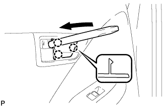
Using a moulding remover, disengage the 3 claws and remove the rear door inside handle bezel plug.
-
-
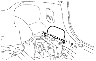
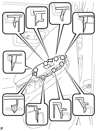
REMOVE DOOR ASSIST GRIP COVER
-
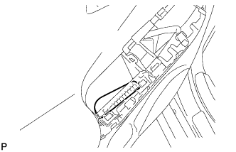
Using a moulding remover, disengage the 6 claws, 2 clips and 3 guides, and remove the door assist grip cover.
-
-
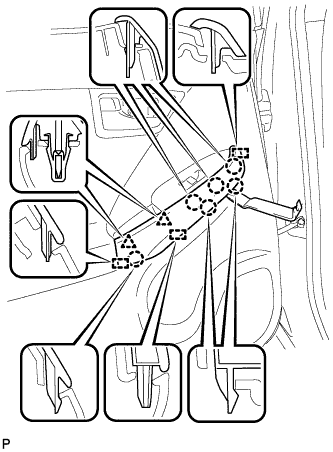
REMOVE REAR POWER WINDOW REGULATOR SWITCH ASSEMBLY WITH REAR DOOR ARMREST BASE PANEL
-
Disengage the 7 claws and 2 guides.
-
Disconnect the connector and remove the rear power window regulator switch assembly with rear door armrest base panel.
-
-
REMOVE REAR DOOR ARMREST COVER
-
Remove the rear door armrest cover.
-
-
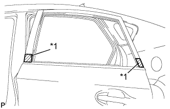
REMOVE REAR DOOR TRIM BOARD SUB-ASSEMBLY
-
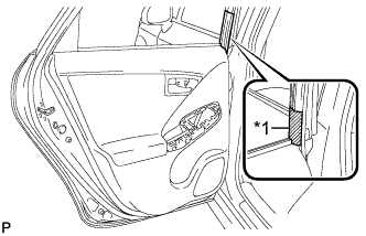
Text in Illustration *1 Protective Tape Put protective tape around the rear door panel.
-
Remove the 2 screws.
-
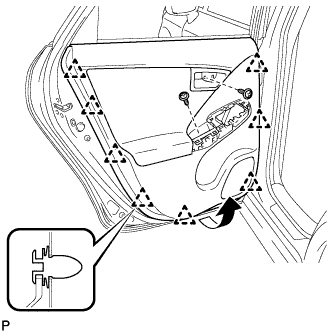
Using a clip remover, disengage the 8 clips.
-
Pull out the rear door trim board sub-assembly in the direction indicated by the arrow in the illustration.
-
Raise the rear door trim board sub-assembly and remove the rear door trim board sub-assembly together with the rear door inner glass weatherstrip.
-
Disengage the 2 claws and disconnect the rear door inside handle sub-assembly.
-
for 8 Speakers:
-
Disconnect the connector.
-
-
-
REMOVE REAR DOOR INSIDE HANDLE SUB-ASSEMBLY
-
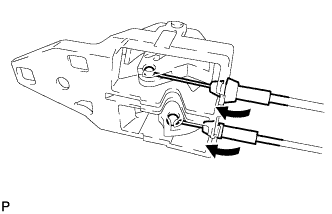
Disconnect the rear door lock remote control cable assembly and rear door inside locking cable assembly, and remove the rear door inside handle sub-assembly.
-
-
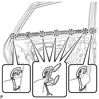
REMOVE REAR DOOR INNER GLASS WEATHERSTRIP
-
Disengage the 7 claws and remove the rear door inner glass weatherstrip from the rear door trim board sub-assembly as shown in the illustration.
-
-
REMOVE REAR NO. 2 SPEAKER ASSEMBLY (for 8 Speakers)
-
Remove the 2 screws and rear No. 2 speaker assembly.
-
-
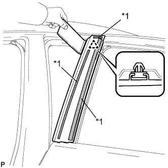
REMOVE REAR DOOR FRAME GARNISH
-
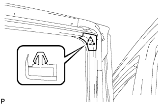
Disengage the clip and remove the rear door frame garnish.
Tech Tips
This garnish needs to be replaced with a new one because the clip will break when removing the rear door frame garnish.
-
-
REMOVE REAR SPEAKER ASSEMBLY
-
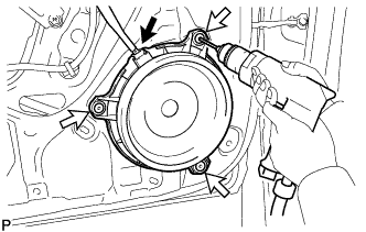
Disconnect the connector.
-
Using a drill bit with a diameter of less than 5 mm (0.197 in.), drill out the 3 rivet heads and remove the rear speaker assembly.
Note
-
Do not touch the cone part of the speaker.
-
Do not drill the rivet at an angle as this will cause damage to the drill and drill hole. Line up the drill and rivet, and carefully drill out the rivet head.
-
Be careful as the cut rivet will be very hot.
-
-
Continue drilling and push out the remaining rivet fragments.
-
Using a vacuum cleaner, remove the rivet fragments and shavings from the inside of the door.
-
-
REMOVE REAR DOOR TRIM BRACKET
-
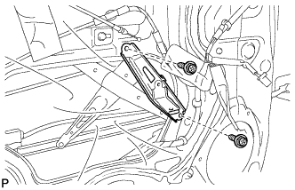
Remove the 2 screws and rear door trim bracket.
-
-
REMOVE REAR DOOR SERVICE HOLE COVER
-
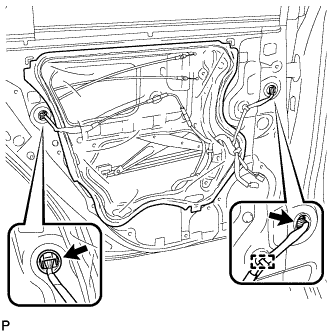
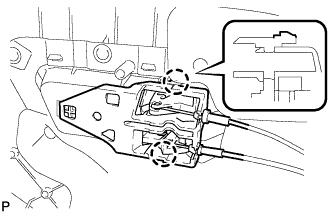
Disconnect the 2 connectors.
-
Disengage the clamp.
-
Pass the rear door lock remote control cable, rear door inside locking cable and each connector through the rear door service hole cover.
-
Remove the rear door service hole cover.
Tech Tips
Remove any remaining butyl tape from the door.
-
-
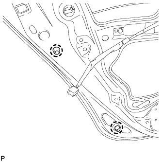
REMOVE REAR DOOR CHECK ASSEMBLY
-
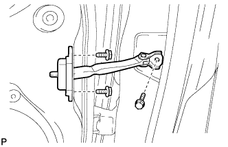
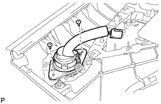
Remove the 3 bolts and rear door check assembly.
-
-
REMOVE REAR DOOR WEATHERSTRIP
-
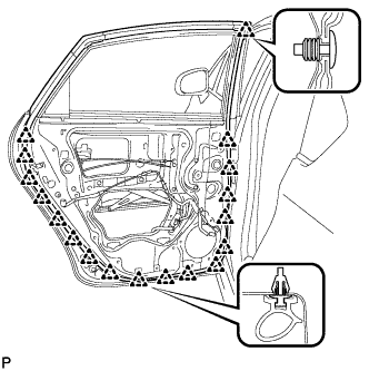
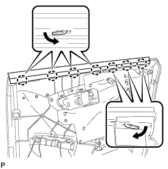
Using a clip remover, disengage the 18 clips and remove the front door weatherstrip.
-
-
REMOVE REAR DOOR GLASS RUN
-
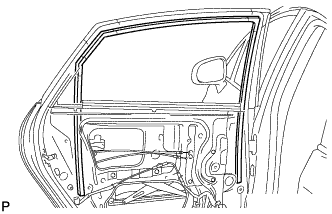
Remove the rear door glass run.
-
-
REMOVE REAR DOOR WINDOW GUIDE SUB-ASSEMBLY
-
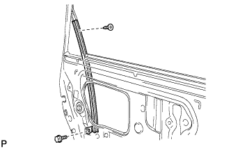
Remove the screw.
-
Remove the bolt and rear door window guide sub-assembly.
-
-
REMOVE REAR DOOR REAR GUIDE SEAL
-
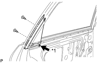
Text in Illustration *1 Temporary Screw Loosen the temporary screw.
-
Remove the 2 screws and rear door rear guide seal.
-
Remove the temporary screw from the rear door rear guide seal.
-
-
REMOVE REAR DOOR GLASS SUB-ASSEMBLY
-
Connect the cable to the negative (-) auxiliary battery terminal and rear power window regulator switch assembly.
-
Connect the rear power window regulator motor connector.
-
Move the rear door glass sub-assembly so that the door glass bolts can be seen.
-
Disconnect the cable from the negative (-) auxiliary battery terminal.
-
Disconnect the rear power window regulator switch assembly and rear power window regulator motor connector.
-
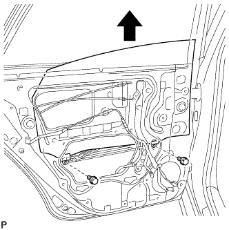
Remove the 2 bolts and rear door glass sub-assembly as shown in the illustration.
Note
-
After the bolts are removed, do not allow the door glass to fall.
-
Do not damage the door glass.
-
-
-
REMOVE REAR DOOR WINDOW REGULATOR ASSEMBLY
-
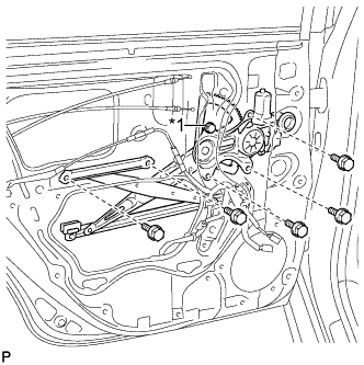
Text in Illustration *1 Temporary Bolt Loosen the temporary bolt.
Note
Do not remove the temporary bolt. If the temporary bolt is removed, the rear door window regulator may fall and cause damage.
-
Remove the 5 bolts.
-
Remove the rear door window regulator assembly.
-
Remove the temporary bolt from the rear door window regulator assembly.
-
-
REMOVE REAR POWER WINDOW REGULATOR MOTOR ASSEMBLY
-
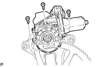
Using a T25 "TORX" socket wrench, remove the 3 screws and rear power window regulator motor assembly.
-
-
REMOVE REAR DOOR LOCK ASSEMBLY (w/o Double Locking System)
-
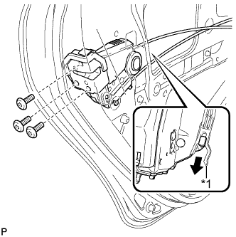
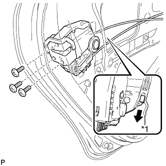
Using a T30 "TORX" socket wrench, remove the 3 screws.
-
Move the rear door lock assembly downward and pull the release plate out of the rear door outside handle frame.
Text in Illustration *1 Release Plate -
Remove the door lock wiring harness seal from the rear door lock assembly.
-
-
REMOVE REAR DOOR LOCK ASSEMBLY (w/ Double Locking System)
-
Using a T30 "TORX" socket wrench, remove the 3 screws.
-
Move the rear door lock assembly downward and pull the release plate out of the rear door outside handle frame.
Text in Illustration *1 Release Plate -
Remove the door lock wiring harness seal from the rear door lock assembly.
-
-
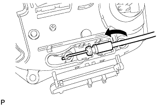
REMOVE REAR DOOR LOCK REMOTE CONTROL CABLE ASSEMBLY (w/o Double Locking System)
-
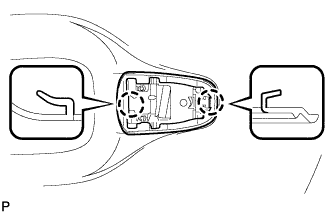
Using a screwdriver, disengage the 2 claws as shown in the illustration.
Tech Tips
Tape the screwdriver tip before use.
-
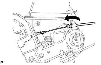
Remove the rear door lock remote control cable assembly as shown in the illustration.
-
-
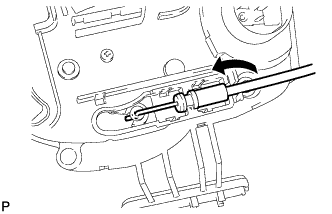
REMOVE REAR DOOR LOCK REMOTE CONTROL CABLE ASSEMBLY (w/ Double Locking System)
-
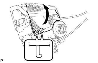
Using a screwdriver, disengage the 2 claws as shown in the illustration.
Tech Tips
Tape the screwdriver tip before use.
-
Remove the rear door lock remote control cable assembly as shown in the illustration.
-
-
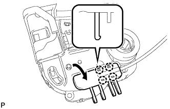
REMOVE REAR DOOR INSIDE LOCKING CABLE ASSEMBLY (w/o Double Locking System)
-
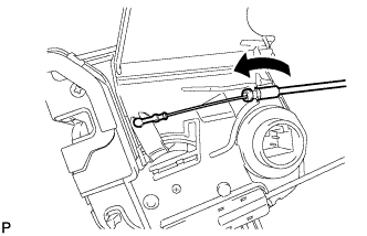
Using a screwdriver, disengage the 4 claws as shown in the illustration.
Tech Tips
Tape the screwdriver tip before use.
-
Remove the rear door inside locking cable assembly as shown in the illustration.
-
-
REMOVE REAR DOOR INSIDE LOCKING CABLE ASSEMBLY (w/ Double Locking System)
-
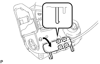
Using a screwdriver, disengage the 4 claws as shown in the illustration.
Tech Tips
Tape the screwdriver tip before use.
-
Remove the rear door inside locking cable assembly as shown in the illustration.
-
-
REMOVE REAR DOOR OUTSIDE HANDLE COVER
-
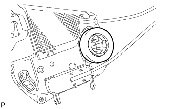
Using a T30 "TORX" socket wrench, loosen the screw.
Tech Tips
The screw cannot be removed because it is integrated into the rear door outside handle frame sub-assembly.
-
Disengage the claw and remove the rear door outside handle cover.
-
-
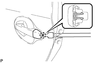
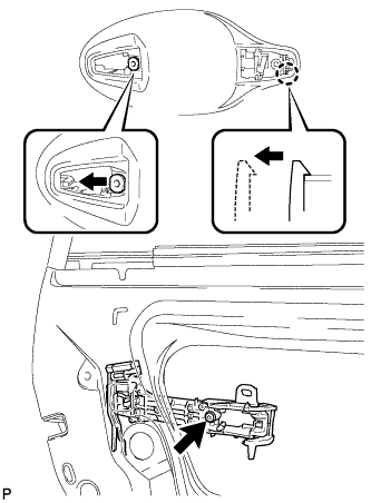
REMOVE REAR DOOR OUTSIDE HANDLE ASSEMBLY
-
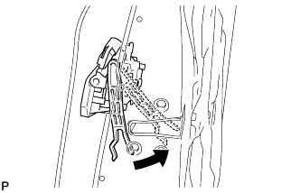
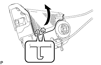
Pull and hold the release plate of the rear door outside handle frame sub-assembly as shown in the illustration.
Note
The release plate may interfere with the rear door outside handle assembly and may be damaged when removing the rear door outside handle assembly, unless the release plate of the rear door outside handle frame sub-assembly is pulled and held.
-
Move the lever in the direction indicated by the arrow in the illustration.
-
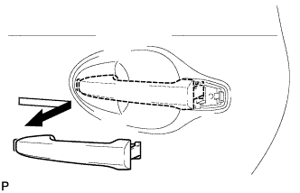
Remove the rear door outside handle assembly as shown in the illustration.
-
-
REMOVE REAR DOOR FRONT OUTSIDE HANDLE PAD
-
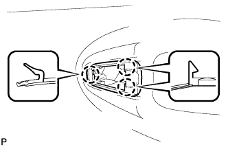
Disengage the 3 claws and remove the rear door front outside handle pad.
-
-
REMOVE REAR DOOR REAR OUTSIDE HANDLE PAD
-
Disengage the 2 claws and remove the rear door rear outside handle pad.
-
-
REMOVE REAR DOOR OUTSIDE HANDLE FRAME SUB-ASSEMBLY
-
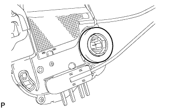
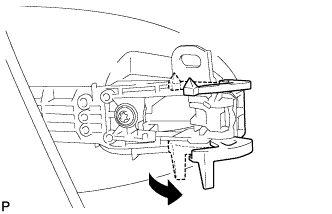
Using a T30 "TORX" socket wrench, loosen the screw.
-
Slide the rear door outside handle frame sub-assembly to disengage the door handle nut and claw of the rear door outside handle frame sub-assembly, and then remove it.
-
-
REMOVE REAR DOOR PANEL CUSHION
-
Disengage the 2 claws and remove the 2 rear door panel cushions.
-
-
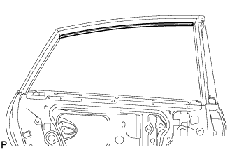
REMOVE REAR DOOR BELT MOULDING ASSEMBLY
-
Text in Illustration *1 Protective Tape Put protective tape around the rear door belt moulding assembly.
-
Using a screwdriver, disengage the 7 claws and remove the rear door belt moulding assembly.
-
-
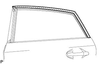
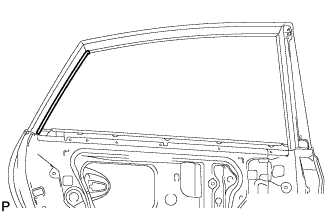
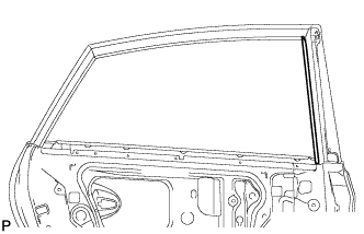
REMOVE REAR DOOR FRONT WINDOW FRAME MOULDING
Tech Tips
When removing the rear door front window frame moulding, heat the vehicle body and rear door front window frame moulding using a heat light.
Heating Temperature Item Temperature Vehicle Body 40 to 60°C (104 to 140°F) Moulding 20 to 30°C (68 to 86°F) Note
Do not heat the vehicle body or rear door front window frame moulding moulding excessively.
-
Using a heat light, heat the rear door front window frame moulding.
-
Text in Illustration *1 Double-sided Tape Using a moulding remover, remove the clip and rear door front window frame moulding.
-
-
REMOVE NO. 2 BLACK OUT TAPE
-
Using a heat light, heat the No. 2 black out tape and vehicle body.
Heating Temperature Item Temperature Vehicle Body 40 to 60°C (104 to 140°F) Note
Do not heat the vehicle body excessively.
-
Pull back on one of the ends of the No. 2 black out tape to remove it.
Tech Tips
When pulling on the tape, pull it parallel to the body.
-
-
REMOVE REAR DOOR OUTSIDE STRIPE
-
Using a heat light, heat the rear door outside stripe and vehicle body.
Heating Temperature Item Temperature Vehicle Body 40 to 60°C (104 to 140°F) Note
Do not heat the vehicle body excessively.
-
Pull back on one of the ends of the rear door outside stripe to remove it.
Tech Tips
When pulling on the stripe, pull it parallel to the body.
-
-
REMOVE REAR DOOR UPPER OUTSIDE STRIPE
-
Using a heat light, heat the rear door upper outside stripe and vehicle body.
Heating Temperature Item Temperature Vehicle Body 40 to 60°C (104 to 140°F) Note
Do not heat the vehicle body excessively.
-
Pull back on one of the ends of the rear door upper outside stripe to remove it.
Tech Tips
When pulling on the stripe, pull it parallel to the body.
-
-
REMOVE REAR DOOR LOWER OUTSIDE STRIPE
-
Using a heat light, heat the rear door lower outside stripe and vehicle body.
Heating Temperature Item Temperature Vehicle Body 40 to 60°C (104 to 140°F) Note
Do not heat the vehicle body excessively.
-
Pull back on one of the ends of the rear door lower outside stripe to remove it.
Tech Tips
When pulling on the stripe, pull it parallel to the body.
-