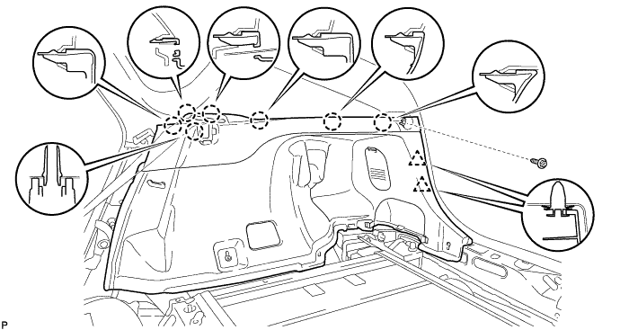
REAR AIRBAG SENSOR REMOVAL
Tech Tips
-
Use the same procedure for the RH side and LH side.
-
The procedure listed below is for the LH side.
-
PRECAUTION
CAUTION:
Be sure to read Precaution thoroughly before servicing Click here.
Note
After turning the power switch off, waiting time may be required before disconnecting the cable from the negative (-) auxiliary battery terminal. Therefore, make sure to read the disconnecting the cable from the negative (-) auxiliary battery terminal notices before proceeding with work Click here.
-
REMOVE REAR NO. 2 FLOOR BOARD (for RH Side)
-
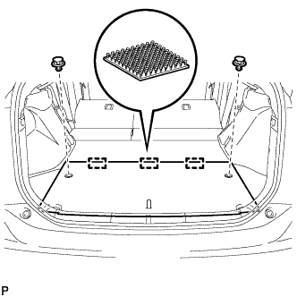
Using a clip remover, remove the 2 clips.
-
Disengage the 3 fasteners and remove the rear No. 2 floor board.
-
-
REMOVE REAR NO. 3 FLOOR BOARD
-
Remove the rear No. 3 floor board.
-
-
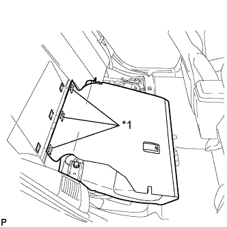
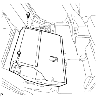
REMOVE DECK FLOOR BOX RH
for LH Side: Click here
for RH Side: Click here
-
REMOVE REAR NO. 3 FLOOR BOARD UPPER PLATE
-
Disengage the 2 claws and remove the rear No. 3 floor board upper plate.
-
-
DISCONNECT CABLE FROM NEGATIVE AUXILIARY BATTERY TERMINAL
CAUTION:
Wait at least 90 seconds after disconnecting the cable from the negative (-) auxiliary battery terminal to disable the SRS system.
Note
When disconnecting the cable, some systems need to be initialized after the cable is reconnected Click here.
-
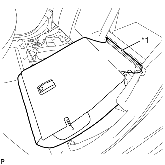
REMOVE REAR SEAT CUSHION ASSEMBLY
-
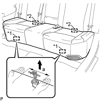
Text in Illustration *1 Front Hook *2 Rear Hook Disengage the front hook of the rear seat cushion assembly from the vehicle body as shown in the illustration.
Standard Measurement Dimension Measurement a 100 mm (3.94 in.) or less Note
Follow the instructions below carefully as the cushion frame can be deformed easily.
-
Choose a front hook to disengage first. Place your hands near the front hook as shown in the illustration. Then lift the seat cushion to disengage the front hook.
-
Repeat the above procedure for the other hook.
-
-
Disengage the 2 rear hooks of the rear seat cushion assembly from the rear seatback assembly.
-
Remove the rear seat cushion assembly.
Note
Be careful not to damage the vehicle body.
-
-
REMOVE REAR SIDE SEATBACK ASSEMBLY LH (for LH Side)
-
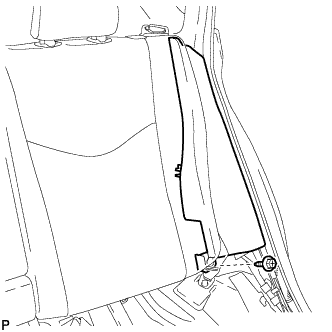
Remove the bolt.
-
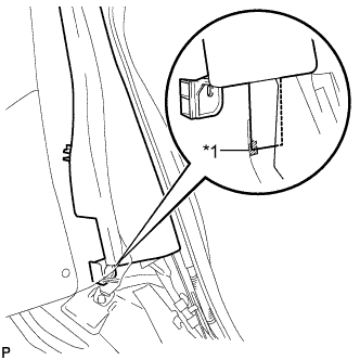
Text in Illustration *1 Fastener Disengage the fastener.
-
Disengage the 2 guides and remove the rear side seatback assembly LH as shown in the illustration.
-
-
DISCONNECT REAR CENTER SEAT BELT ASSEMBLY (for RH Side)
-
Remove the bolt and disconnect the anchor part of the rear center seat belt assembly.
-
-
REMOVE REAR SEAT HEADREST ASSEMBLY (for RH Side)
-
REMOVE REAR SEAT CENTER HEADREST ASSEMBLY (for RH Side)
-
REMOVE REAR SEATBACK ASSEMBLY RH (for RH Side)
-
Fold the rear seatback assembly RH forward.
-
Text in Illustration *1 Fastener Disengage the 3 fasteners.
-
Remove the 2 bolts and rear seatback assembly RH.
Note
Be careful not to damage the vehicle body.
-
-
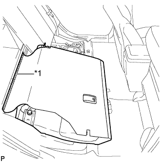
REMOVE TONNEAU COVER ASSEMBLY (for RH Side)
-
Remove the tonneau cover assembly.
-
-
REMOVE REAR NO. 4 FLOOR BOARD SUB-ASSEMBLY (for RH Side)
-
Remove the rear No.4 floor board sub-assembly.
-
-
REMOVE DECK FLOOR BOX LH (for RH Side)
Tech Tips
Use the same procedure for the LH side and RH side Click here.
-
REMOVE REAR NO. 2 FLOOR BOARD SUB-ASSEMBLY (for RH Side)
-
Disengage the claw and 2 clips, and remove the rear No. 2 floor board sub-assembly.
-
-
REMOVE REAR NO. 1 FLOOR BOARD SUB-ASSEMBLY (for RH Side)
-
Disengage the claw and 3 clips, and remove the rear No. 1 floor board sub-assembly.
-
-
REMOVE REAR NO. 1 FLOOR BOARD (for RH Side)
-
Fold the rear seatback assembly LH forward.
-
Text in Illustration *1 Fastener Disengage the fastener.
-
Fold the rear seatback assembly LH forward.
-
Text in Illustration *1 Fastener Disengage the fastener.
-
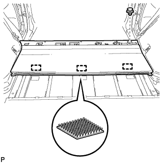
Using a clip remover, remove the clip.
-
Disengage the 3 fasteners and remove the rear No. 1 floor board.
-
-
REMOVE DECK TRIM SERVICE HOLE COVER (for RH Side)
-
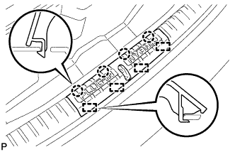
Disengage the 4 claws.
-
Disengage the 4 guides and remove the deck trim service hole cover.
-
-
REMOVE REAR DECK TRIM COVER (for RH Side)
-
Disengage the 4 claws and remove the rear deck trim cover.
-
-
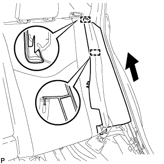
REMOVE REAR SIDE SEATBACK ASSEMBLY RH (for RH Side)
-
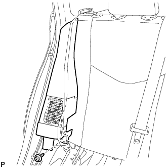
Remove the bolt.
-
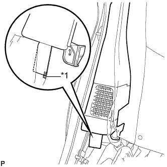
Text in Illustration *1 Fastener Disengage the fastener.
-
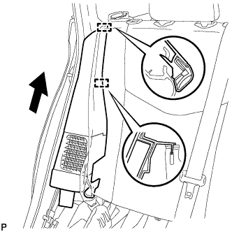
Disengage the 2 guides and remove the rear side seatback assembly RH as shown in the illustration.
-
-
REMOVE LUGGAGE HOLD BELT STRIKER ASSEMBLY (for RH Side)
Tech Tips
Use the same procedure for the RH side and LH side Click here.
-
REMOVE TONNEAU COVER HOLDER CAP (for RH Side)
-
Text in Illustration *1 Protective Tape Using a screwdriver, disengage the claw and remove the tonneau cover holder cap.
Tech Tips
Tape the screwdriver tip before use.
-
-
REMOVE DECK TRIM SIDE PANEL ASSEMBLY RH (for RH Side)
-
Remove the screw.
-
Disengage the 7 claws and 2 clips, and remove the deck trim side panel assembly RH.
-
-
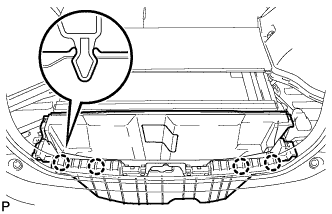
REMOVE NO. 2 HYBRID BATTERY INTAKE DUCT (for RH Side)
-
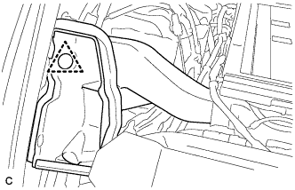
Remove the clip and No. 2 hybrid battery intake duct.
-
-
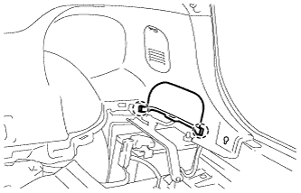
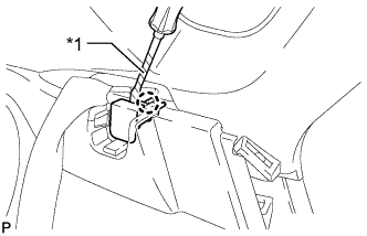
REMOVE SIDE NO. 2 AIRBAG SENSOR ASSEMBLY
-
Check that the power switch is off.
-
Check that the cable is disconnected from the negative (-) auxiliary battery terminal.
CAUTION:
Wait at least 90 seconds after disconnecting the cable from the negative (-) auxiliary battery terminal to disable the SRS system.
-
Disconnect the connector from the side No. 2 airbag sensor assembly.
Note
When disconnecting any airbag connector, take care not to damage the airbag wire harness.
-
While holding the sides of the outer connector locking sleeve, slide the sleeve in the direction indicated by the arrow shown in the illustration.
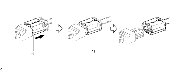
Text in Illustration *1 Outer Connector Locking Sleeve - - -
When the connector lock is released, the connectors can be disconnected.
Tech Tips
Be sure to hold both outer flank sides. Holding the top and bottom will make disconnection difficult.
-
-
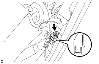
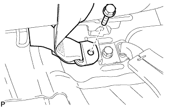
Remove the nut and side No. 2 airbag sensor assembly from the vehicle body.
Note
Loosen the nut while holding the side No. 2 airbag sensor assembly because the side No. 2 airbag sensor assembly pin (stopper) is easily damaged.
-