FUEL TANK REMOVAL

-
DISCHARGE FUEL SYSTEM PRESSURE
CAUTION:
-
Do not disconnect any part of the fuel system until you have discharged the fuel system pressure.
-
Even after discharging the fuel pressure, place a cloth or equivalent over fittings as you separate them to reduce the risk of fuel spray on yourself or in the engine compartment.
-
Disconnect the cable from the negative (-) battery terminal.
CAUTION:
Wait at least 90 seconds after disconnecting the cable from the negative (-) battery terminal to prevent airbag and seat belt pretensioner activation.
-
Remove the front driver side scuff plate.
-
Using a screwdriver, detach the 7 claws.
Tech Tips
Tape the screwdriver tip before use.
-
Using a clip remover, detach the 3 clips and remove the scuff plate.
-
-
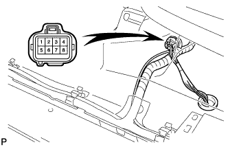
Turn up the floor carpet and disconnect the joining connector, as shown in the illustration.
Tech Tips
This connector has the lines of the fuel pump and rear speed sensor.
-
Connect the cable to the negative (-) battery terminal.
-
Start the engine. After the engine has stopped on its own, turn the ignition switch OFF.
Tech Tips
DTC C0210/33 and DTC C0215/34 (rear speed sensor circuit) and DTC P0171/25 (system too lean) may be set.
-
Crank the engine again, and then check that the engine does not start.
-
Loosen the fuel tank cap, and then discharge the pressure in the fuel tank completely.
-
Connect the fuel pump connector.
-
Install the front driver side scuff plate.
-
Clear the DTCs Click here.
-
-
DISCONNECT CABLE FROM NEGATIVE BATTERY TERMINAL
Note
When disconnecting the cable, some systems need to be initialized after the cable is reconnected Click here.
-
REMOVE FUEL TANK CAP ASSEMBLY
-
REMOVE FUEL TANK PROTECTOR
-
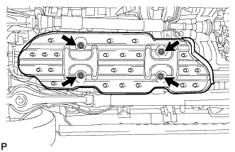
Remove the 4 nuts and fuel tank protector.
-
-
REMOVE NO. 3 FUEL TUBE CLAMP
-
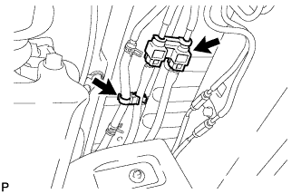
Remove the 2 tube clamps from the fuel tube.
-
-
DISCONNECT FUEL TANK MAIN TUBE SUB-ASSEMBLY AND FUEL TANK RETURN TUBE
-
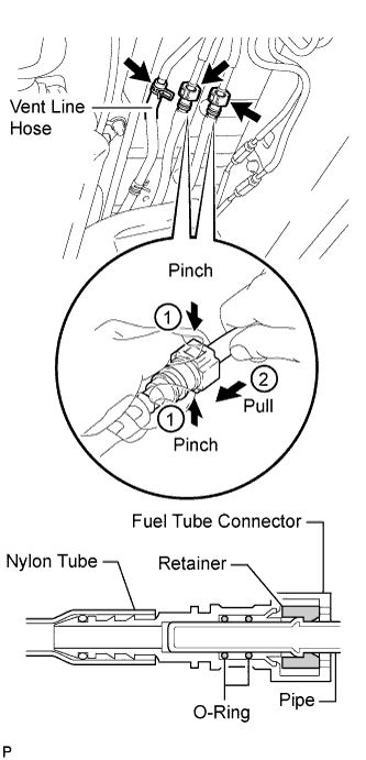
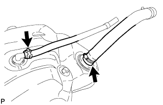
Pinch and pull the fuel tank main tube connector to disconnect the connector from the pipe. Then pinch and pull the fuel tank return tube connector to disconnect the connector from the pipe.
Note
-
Remove any dirt and foreign objects from the fuel tube connector before performing this work.
-
Do not allow any scratches or foreign objects on the parts when disconnecting, as the fuel tube connector contains the O-rings that seal the pipe.
-
Perform this work by hand. Do not use any tools.
-
Do not forcibly bend, twist or turn the nylon tube.
-
Keep the plug free from foreign objects.
-
Protect the disconnected part by covering it with a plastic bag after disconnecting the fuel tube.
-
If the fuel tube connector and pipe are stuck, push and pull to release them.
-
-
Disconnect the vent line hose from the fuel pipe.
-
-
DISCONNECT FUEL TANK BREATHER HOSE
-
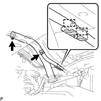
Disconnect the fuel tank breather hose from the fuel tank filler pipe.
-
Detach the fuel tank breather hose from the 2 clamps.
-
-
DISCONNECT FUEL TANK TO FILLER PIPE HOSE
-
Disconnect the fuel tank to filler pipe hose from the fuel tank filler pipe.
-
-
REMOVE FUEL TANK FILLER PIPE
-
Remove the bolt, nut and filler pipe.
-
-
REMOVE FUEL TANK ASSEMBLY
-
Place a transmission jack under the fuel tank.
-
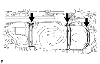
Remove the 3 bolts, 3 clips, 3 pins and 3 fuel tank bands.
-
Slightly lower the transmission jack.
Note
Be careful not to cut the wiring.
-
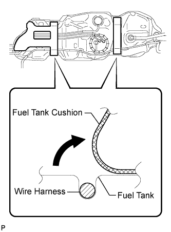
Fold back approximately half of each cushion so that the wire harness can be removed in the step below.
-
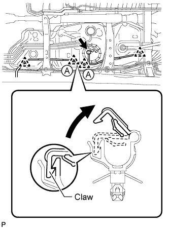
Detach the wire harness from the 4 clamps shown in the illustration.
Tech Tips
Detach the claw of the clamps labeled A in the illustration to detach the wire harness.
-
Disconnect the fuel pump and sender gauge connector.
-
-
REMOVE NO. 1 FUEL TANK PROTECTOR SUB-ASSEMBLY
-
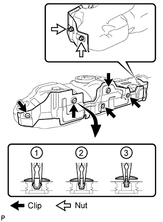
Using needle-nose pliers, remove the 5 clips and 2 nuts shown in the illustration and then remove the No. 1 fuel tank protector.
-
-
REMOVE FUEL TANK CUSHION
-
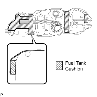
Remove the 4 fuel tank cushions from the fuel tank.
-
-
REMOVE NO. 1 FUEL EVAPORATION TUBE SUB-ASSEMBLY
-
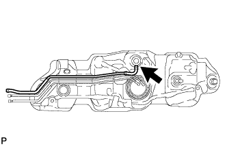
Remove the No. 1 fuel evaporation tube.
-
-
REMOVE FUEL PUMP GAUGE RETAINER
-
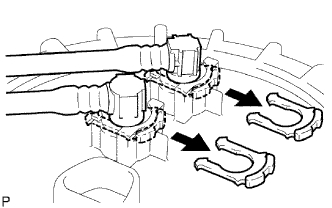
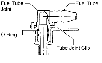
Remove the 2 tube joint clips and pull out the 2 fuel tank tubes.
Note
-
-
Remove any dirt and foreign matter on the fuel tube joint before performing this work.
-
Do not allow any scratches or foreign matter on the parts when disconnecting them, as the fuel tube joint contains the O-rings that seal the plug.
-
Perform this work by hand. Do not use any tools.
-
Do not forcibly bend, twist or turn the nylon tube.
-
Protect the disconnected part by covering it with a plastic bag and tape after disconnecting the fuel tubes.
-
-
Remove the fuel tank return tube and fuel tank main tube from the fuel tank.
-
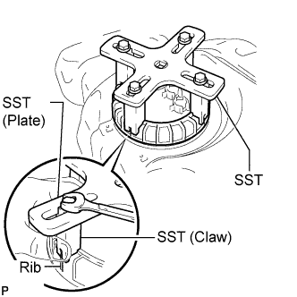
Temporarily install SST (plate and 4 claws) to the fuel pump gauge retainer.
- SST
- 09808-14030
Tech Tips
-
Be sure to use 4 SST (claws) as shown in the illustration.
-
Engage SST (claws) securely with the fuel pump gauge retainer ribs to secure SST.
-
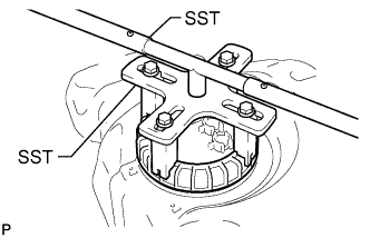
While pressing SST (claws) against the fuel pump gauge retainer ribs securely, install the 4 bolts.
Tech Tips
Install SST while pressing SST (claws) against the fuel pump gauge retainer (towards the center of SST).
-
Install SST (handle).
-
Lightly press down on SST to prevent it from separating from the fuel pump gauge retainer. While pressing SST, rotate the handle slowly to loosen the fuel pump gauge retainer.
- SST
- 09808-14030
Note
-
When the retainer is loosened, be careful as the fuel pump will spring upward from the force of the spring.
-
Do not use any tools other than specified in this operation. Damage to the fuel pump gauge retainer or the fuel tank may result.
-
Do not press down on SST excessively as this may make the fuel pump gauge retainer hard to rotate, and may damage components.
-
Make sure to rotate SST (handle) horizontally. If SST (handle) is rotated at an angle, SST may come off.
-
Do not spin SST too fast or use an impact wrench as this may result in damage to components.
-
If SST comes off of the fuel pump gauge retainer, loosen SST (bolts) and reinstall SST.
Tech Tips
The tips of SST (claws) can be fitted onto the ribs of the fuel pump gauge retainer.
-
Remove the fuel pump gauge retainer.
-
Remove the fuel pump gauge retainer.
-
-
REMOVE FUEL SUCTION WITH PUMP AND GAUGE TUBE ASSEMBLY
-
Remove the fuel suction with pump and gauge tube from the fuel tank.
Note
Be careful not to bend the arm of the fuel sender gauge.
-
Remove the gasket from the fuel tank.
-
-
REMOVE FUEL TANK BREATHER HOSE
-
Remove the fuel tank breather hose from the fuel tank.
-
-
REMOVE FUEL TANK TO FILLER PIPE HOSE
-
Remove the fuel tank to filler pipe hose from the fuel tank.
-