ENGINE ASSEMBLY REMOVAL

-
DISCHARGE FUEL SYSTEM PRESSURE
CAUTION:
-
Do not disconnect any part of the fuel system until you have discharged the fuel system pressure.
-
Even after discharging the fuel pressure, place a cloth or equivalent over fittings as you separate them to reduce the risk of fuel spray on yourself or in the engine compartment.
-
Disconnect the cable from the negative (-) battery terminal.
CAUTION:
Wait at least 90 seconds after disconnecting the cable from the negative (-) battery terminal to prevent airbag and seat belt pretensioner activation.
-
Remove the front driver side scuff plate.
-
Using a screwdriver, detach the 7 claws.
Tech Tips
Tape the screwdriver tip before use.
-
Using a clip remover, detach the 3 clips and remove the scuff plate.
-
-
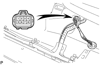
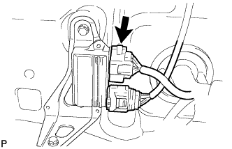
Turn up the floor carpet and disconnect the joining connector, as shown in the illustration.
Tech Tips
This connector has the lines of the fuel pump and rear speed sensor.
-
Connect the cable to the negative (-) battery terminal.
-
Start the engine. After the engine has stopped on its own, turn the ignition switch OFF.
Tech Tips
DTC C0210/33 and DTC C0215/34 (rear speed sensor circuit) and DTC P0171/25 (system too lean) may be set.
-
Crank the engine again, and then check that the engine does not start.
-
Loosen the fuel tank cap, and then discharge the pressure in the fuel tank completely.
-
Connect the fuel pump connector.
-
Install the front driver side scuff plate.
-
Clear the DTCs Click here.
-
-
DISCONNECT CABLE FROM NEGATIVE BATTERY TERMINAL
CAUTION:
Wait at least 90 seconds after disconnecting the cable from the negative (-) battery terminal to prevent airbag pretensioner activation.
-
REMOVE NO. 1 ENGINE UNDER COVER
-
Remove the 4 bolts and under cover.
-
Remove the 3 clips, 3 bolts and side cover RH.
-
Remove the 3 clips, 3 bolts and side cover LH.
-
-
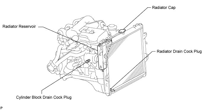
DRAIN ENGINE COOLANT
-
Remove the radiator cap.
-
Loosen the cylinder block drain cock plug and radiator drain cock plug, and then drain the coolant.
Tech Tips
Collect the coolant in a container and dispose of it according to the regulations in your area.
-
-
DRAIN ENGINE OIL
-
Remove the oil filler cap.
-
Remove the oil drain plug and drain the oil into a container.
-
-
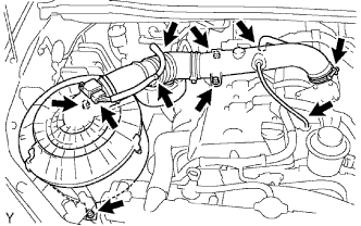
REMOVE INTAKE AIR CONNECTOR AND AIR CLEANER ASSEMBLY
-
Disconnect the vacuum hose.
-
Disconnect the No. 2 ventilation hose.
-
Disconnect the MAF meter connector and wire harness clamps.
-
Loosen the hose clamp and remove the 4 bolts, air cleaner and intake air connector assembly.
-
-
REMOVE RADIATOR GRILLE
-
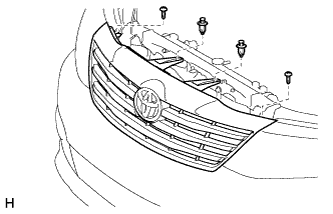
Remove the 2 clips and 2 screws.
-
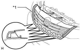
Text in Illustration *1 Protective Tape Put protective tape around the radiator grille.
-
Detach the 6 claws and remove the radiator grille.
-
-
DISCONNECT RADIATOR INLET HOSE
-
DISCONNECT RADIATOR OUTLET HOSE
-
REMOVE DRIVE BELT
-
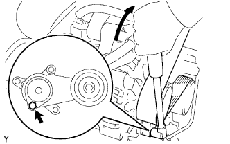
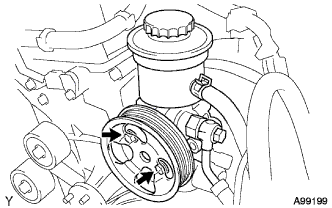
Use the hexagon-shaped part indicated by the arrow in the illustration to move the tensioner pulley downward and decrease the tension in the drive belt. Then remove the drive belt.
Note
When removing the drive belt, do not use the idle pulley's bolt.
Tech Tips
After removing the drive belt, move the tensioner upward to the maximum amount.
-
-
REMOVE AIR PUMP INLET (w/ Secondary Air Injection System)
-
Remove the bolt and disconnect the air pump inlet.
-
-
REMOVE FAN SHROUD
-
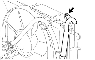
Disconnect the reservoir hose from the radiator tank upper.
-
Loosen the 4 nuts holding the fluid coupling fan.
-
Remove the drive belt Click here.
-
Remove the 2 bolts holding the fan shroud.
-
Remove the 4 nuts holding the fluid coupling fan, and then remove the shroud together with the coupling fan.
Note
Be careful not to damage the radiator core.
-
Remove the fan pulley from the water pump.
-
-
REMOVE FAN PULLEY
-
REMOVE RADIATOR ASSEMBLY
-
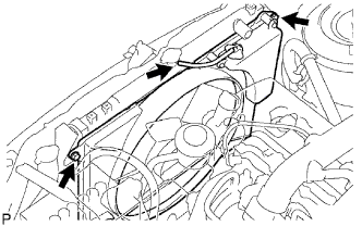
Disconnect the 2 airbag sensor front connectors.
-
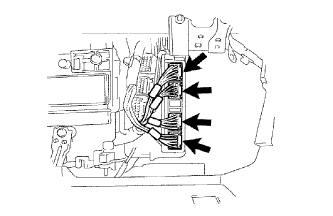
Using a clip remover, detach the 4 clamps shown in the illustration from the radiator side.
Tech Tips
Tape the clip remover tip before use.
-
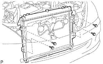
Remove the 4 bolts and radiator.
-
-
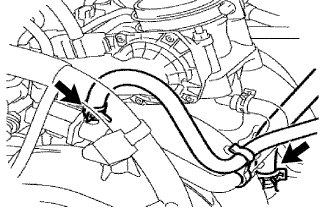
DISCONNECT HOSE
-
Disconnect the vacuum hose (from brake master cylinder).
-
Disconnect the purge line hose from the purge VSV.
-
-
DISCONNECT FUEL HOSE
-
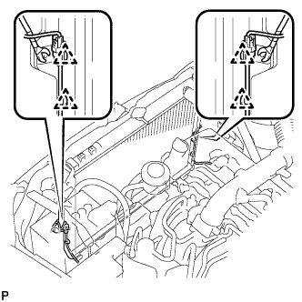
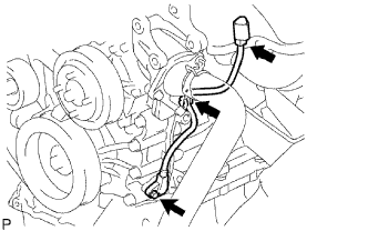
Disconnect the No. 2 fuel hose from the pressure regulator.
-
Disconnect the No. 1 fuel hose from the pulsation damper.
-
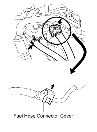
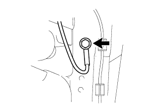
Detach the lock claw by lifting up the cover, as shown in the illustration.
-
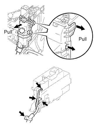
Check for foreign matter on the pipe and around the connector before disconnecting. Clean if necessary.
-
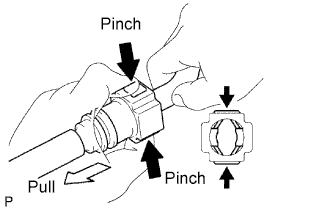
If the connector and the pipe are stuck together, pinch the connector, and push and pull the pipe to disconnect them.
Note
Do not use any tools in this procedure.
-
Check for foreign matter on the seal surface of the disconnected pipe. Clean if necessary.
-
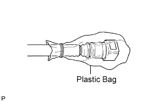
To protect the disconnected pipe and connector from damage and contamination, cover it with a plastic bag.
-
-
-
DISCONNECT ENGINE WIRE
-
Disconnect the ECM connectors from the cabin.
-
Remove the glove compartment door.
-
Disconnect the 4 ECM connectors.
-
-
w/ Secondary air injection system:
Disconnect the air injection driver connector.
-
Detach the wire harness clamp.
-
Remove the bolt and disconnect the ground wire.
-
Pull out the engine wire from the cabin.
-
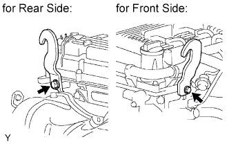
w/ Secondary air injection system:
Disconnect the air fuel ratio sensor connector.
-
w/o Secondary air injection system:
Disconnect the heated oxygen sensor connector.
-
Remove the bolt and disconnect the sensor bracket from the right side of the frame.
-
Remove the bolt and disconnect the ground wire from the left side of the frame.
-
Remove the nut and disconnect the ground wire from the body.
-
Remove the engine room relay block cover (upper).
-
Remove the engine room relay block cover (side).
-
Using a screwdriver, detach the 4 claws and remove the relay block cover.
Tech Tips
Tape the screwdriver tip before use.
-
-
Remove the nut and disconnect the cable from the engine room junction block.
-
Disconnect the 2 engine room junction block connectors and disconnect the wire clamp.
-
Remove the bolt and disconnect the wire clamp from the front engine mounting bracket LH.
-
-
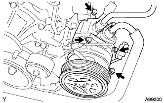
DISCONNECT VANE PUMP
-
Disconnect the oil pressure switch connector.
-
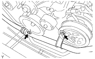
Remove the 2 bolts and disconnect the vane pump from the engine.
-
Support the vane pump securely.
-
-
REMOVE OIL DIPSTICK
-
Remove the oil dipstick.
-
-
REMOVE OIL DIPSTICK GUIDE
-
Remove the bolt, oil dipstick guide and O-ring.
Tech Tips
Cover the oil dipstick guide hole to prevent foreign matter from entering it.
-
-
DISCONNECT COOLER COMPRESSOR FROM ENGINE
-
Disconnect the compressor connector.
-
Remove the 2 bolts and disconnect the suction hose from the engine.
-
Remove the 4 bolts and disconnect the compressor from the engine.
-
Support the cooler compressor securely.
-
-
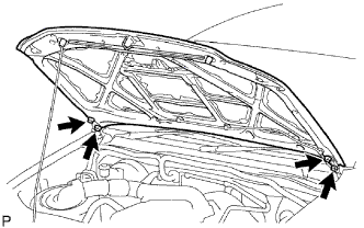
REMOVE HOOD ASSEMBLY
-
Disconnect the washer nozzle hose.
-
Remove the 4 bolts and hood.
Note
Be careful not to damage the vehicle.
-
-
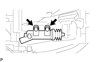
REMOVE FRONT EXHAUST PIPE
-
Remove the 2 bolts and 2 compression springs.
-
Disconnect the front exhaust pipe from the exhaust manifold and remove the gasket.
-
Remove the front exhaust pipe from the exhaust pipe support.
-
-
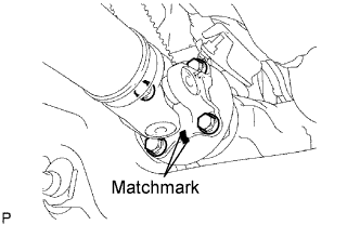
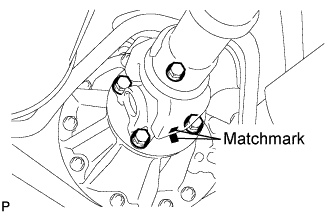
REMOVE FRONT PROPELLER SHAFT ASSEMBLY (for 4WD)
-
Place matchmarks on the propeller shaft flange and differential.
-
Remove the 4 nuts, 4 bolts and 4 washers, and disconnect the propeller shaft.
-
Place matchmarks on the propeller shaft flange and transfer flange.
-
Remove the 4 nuts, 4 washers and front propeller shaft.
-
-
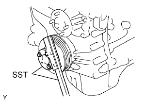
REMOVE PROPELLER SHAFT WITH CENTER BEARING ASSEMBLY (for 2WD)
-
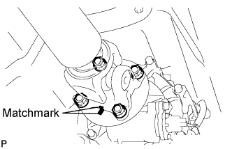
Place matchmarks on the propeller shaft flange and differential flange.
-
Remove the 4 nuts, 4 bolts and 4 washers, and disconnect the propeller shaft.
-
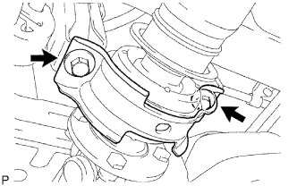
Remove the 2 bolts and 2 plates from the frame crossmember.
-
Pull out the propeller shaft.
-
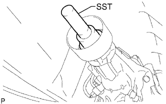
Install SST to the extension housing to prevent oil leakage.
- SST
- 09325-40010
-
-
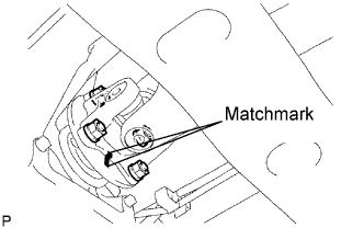
REMOVE REAR PROPELLER SHAFT ASSEMBLY (for 4WD)
-
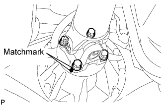
Place matchmarks on the propeller shaft flange and transfer flange.
-
Remove the 4 nuts and 4 washers, and disconnect the propeller shaft.
-
Place matchmarks on the propeller shaft flange and differential flange.
-
Remove the 4 nuts, 4 bolts and 4 washers.
-
Remove the propeller shaft.
-
-
REMOVE STARTER
-
Disconnect the starter connector.
-
Remove the terminal cap.
-
Remove the nut and disconnect the starter wire.
-
Remove the 2 bolts and starter.
-
-
REMOVE CLUTCH RELEASE CYLINDER (for Manual Transmission)
-
Remove the 2 bolts and clutch release cylinder.
-
-
REMOVE MANUAL TRANSMISSION UNIT
-
Remove the manual transmission unit from the vehicle.
If necessary, refer to the corresponding manual transmission section, and perform the work by following the removal procedures for the manual transmission assembly.
-
-
REMOVE AUTOMATIC TRANSMISSION ASSEMBLY
-
Remove the automatic transmission assembly from the vehicle.
If necessary, refer to the corresponding automatic transmission section, and perform the work by following the removal procedures for the automatic transmission assembly.
-
-
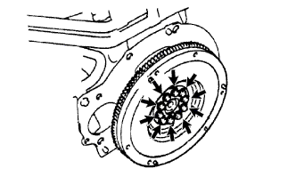
REMOVE CLUTCH COVER (for Manual Transmission)
-
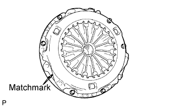
Place matchmarks on the clutch cover and flywheel.
-
Loosen each set bolt one turn at a time until spring tension is released.
-
Remove the 6 set bolts and pull off the clutch cover.
Note
Do not drop the clutch disc.
-
-
REMOVE CLUTCH DISC (for Manual Transmission)
Note
Keep the lining part of the clutch disc, pressure plate and surface of the flywheel away from oil and foreign matter.
-
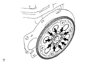
REMOVE FLYWHEEL (for Manual Transmission)
-
Fix the crankshaft in place with SST.
- SST
- 09213-54015 ( 91651-60855 )
- 09330-00021
-
Remove the 10 bolts and flywheel.
-
-
REMOVE DRIVE PLATE (for Automatic Transmission)
-
Fix the crankshaft in place with SST.
- SST
- 09213-54015 ( 91651-60855 )
- 09330-00021
-
Remove the 10 bolts, rear spacer, drive plate and front spacer.
-
-
REMOVE REAR END PLATE
-
Remove the bolt and rear end plate.
-
-
REMOVE ENGINE ASSEMBLY
-
Install the 2 engine hangers as shown in the illustration.
Item Part No. Engine hanger 12281-0C010 Bolt 90105-T0129 - Torque:
- 42 N*m { 428 kgf*cm, 31 ft.*lbf }
-
Attach the engine sling device and chain block to the engine hangers.
-
Remove the 4 bolts and 4 nuts holding the engine mounting bracket and frame.
-
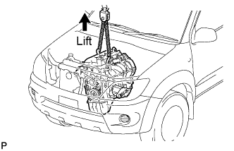
Lift the engine out of the vehicle slowly and carefully.
Note
Make sure to disconnect all the wires, hoses and cables from the engine. Keep the disconnected wires, hoses and cables off of the engine.
-
-
INSTALL ENGINE TO ENGINE STAND
-
Place the engine assembly onto the stand.
-
-
REMOVE IGNITION COIL
-
Disconnect the 4 ignition coil connectors and remove the 4 bolts and 4 ignition coils.
-
-
REMOVE SPARK PLUG
-
REMOVE VENTILATION PIPE
-
Remove the bolt and ventilation pipe.
-
-
REMOVE GENERATOR
-
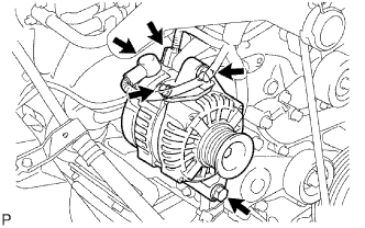
Detach the terminal cap.
-
Remove the nut, bolt and generator wire.
-
Disconnect the generator connector.
-
Remove the 2 bolts and generator.
-
-
REMOVE ENGINE WIRE
-
Disconnect the oil pressure sensor connector.
-
Disconnect the noise filter connector
-
Disconnect the camshaft position sensor connector.
-
Disconnect the 4 injector connectors.
-
Disconnect the crankshaft position sensor connector.
-
Disconnect the oil control valve connector.
-
Disconnect the throttle body connector.
-
Disconnect the engine coolant temperature sensor connector.
-
Disconnect the knock sensor connector.
-
Disconnect the wire harness from the clamps.
-
Remove the 2 bolts and wire harness from the engine.
-
-
REMOVE THROTTLE BODY
-
Disconnect the throttle position sensor and control motor connector.
-
Disconnect the 2 water by-pass hoses.
-
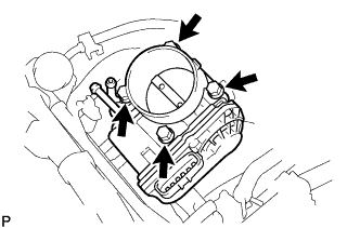
Remove the 4 bolts and throttle body.
-
Remove the gasket.
-
-
REMOVE FUEL DELIVERY PIPE
Note
Be careful not to drop the injectors when removing the delivery pipe.
-
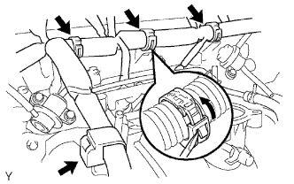
Disconnect the 4 clamps and wire harness from the delivery pipe.
-
Disconnect the vacuum hose.
-
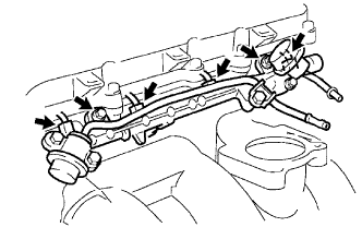
Disconnect the 4 injector connectors.
-
Remove the 2 bolts and delivery pipe together with the 4 injectors.
-
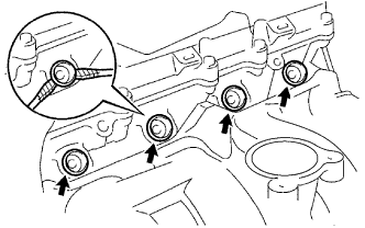
Using 2 screwdrivers, pry out the 4 spacers from the cylinder head.
Tech Tips
Tape the screwdriver tips before use.
-
-
REMOVE INJECTOR
-
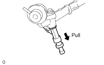
Pull out the 4 injectors from the delivery pipe.
-
-
REMOVE INTAKE MANIFOLD
-
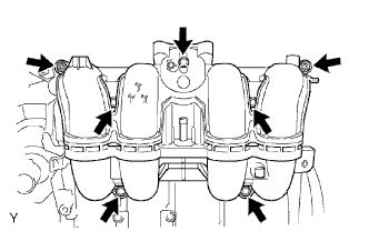
Disconnect the crankshaft position sensor from the clamp.
-
Remove the 5 bolts, 2 nuts, intake manifold and gasket.
-
-
REMOVE EXHAUST MANIFOLD HEAT INSULATOR (w/o Secondary Air Injection System)
-
Remove the 5 bolts and heat insulator.
-
-
REMOVE EXHAUST MANIFOLD HEAT INSULATOR (w/ Secondary Air Injection System)
-
Remove the 5 bolts and exhaust manifold heat insulator.
-
-
REMOVE NO. 4 INTAKE PIPE (w/ Secondary Air Injection System)
-
Remove the 4 nuts, No. 4 intake pipe and 2 gaskets.
-
-
REMOVE AIR SWITCHING VALVE (w/ Secondary Air Injection System)
-
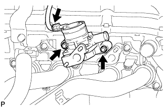
Disconnect the air switching valve connector.
-
Remove the 2 nuts and air switching valve.
-
-
REMOVE EXHAUST MANIFOLD (w/o Secondary Air Injection System)
-
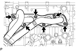
Remove the 6 nuts, exhaust manifold and gasket.
-
-
REMOVE EXHAUST MANIFOLD (w/ Secondary Air Injection System)
-
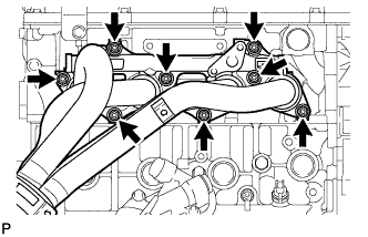
Remove the 8 nuts, exhaust manifold and gasket.
-
-
REMOVE IDLE PULLEY ASSEMBLY
-
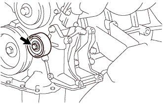
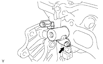
Loosen the bolt, and then remove the idle pulley assembly.
Tech Tips
The bolt in the illustration cannot be removed from the idle pulley assembly.
-
-
REMOVE COMPRESSOR MOUNTING BRACKET
-
Remove the 5 bolts and compressor mounting bracket.
-
-
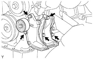
REMOVE V-RIBBED BELT TENSIONER
-
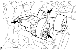
Remove the 3 bolts and belt tensioner.
-
-
REMOVE WATER INLET
-
Remove the bolt, 2 nuts, water inlet and gasket.
-
-
REMOVE THERMOSTAT
-
Remove the thermostat and gasket.
-
-
REMOVE NO. 1 IDLER PULLEY
-
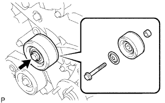
Remove the bolt, pulley plate, idler pulley and spacer.
-
-
REMOVE OIL PRESSURE SWITCH
-
Using a 24 mm deep socket wrench, remove the oil pressure switch.
-
-
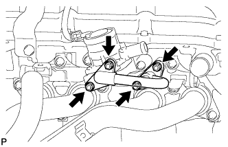
REMOVE NO. 1 WATER BY-PASS PIPE
-
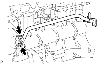
Remove the 2 nuts, water by-pass pipe and gasket.
-
-
REMOVE KNOCK SENSOR
-
Remove the bolt and sensor.
-
-
REMOVE ENGINE COOLANT TEMPERATURE SENSOR
-
Using a 19 mm deep socket wrench, remove the sensor.
-
-
REMOVE CAMSHAFT POSITION SENSOR
-
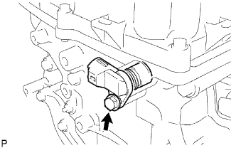
Remove the bolt, sensor and O-ring.
-
-
REMOVE CRANKSHAFT POSITION SENSOR
-
Disconnect the sensor connector.
-
Disconnect the connector from the connector bracket.
-
Detach the harness clamp.
-
Remove the bolt and sensor.
-
-
REMOVE CAMSHAFT TIMING OIL CONTROL VALVE
-
Remove the bolt, oil control valve and O-ring.
-
-
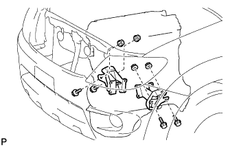
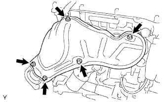
REMOVE FRONT ENGINE MOUNTING BRACKET RH
-
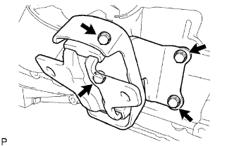
Remove the 4 bolts and mounting bracket.
-
-
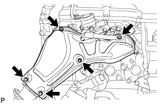
REMOVE FRONT ENGINE MOUNTING BRACKET LH
-
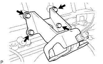
Remove the 4 bolts and mounting bracket.
-