METER / GAUGE SYSTEM Steering Pad Switch Circuit
DESCRIPTION
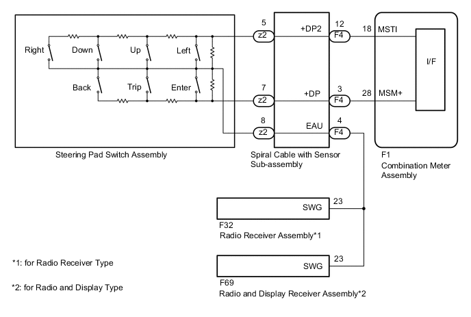
The combination meter assembly and steering pad switch assembly are connected via direct line. The main display and multi-information display in the combination meter assembly are operated using the switches of the steering pad switch assembly.
WIRING DIAGRAM
CAUTION / NOTICE / HINT
Note
When replacing the combination meter assembly, always replace it with a new one.
PROCEDURE
-
INSPECT STEERING PAD SWITCH ASSEMBLY
-
Remove the steering pad switch assembly.
-
Inspect the steering pad switch assembly.
NG 
REPLACE STEERING PAD SWITCH ASSEMBLY Click here
OK 
-
-
INSPECT SPIRAL CABLE WITH SENSOR SUB-ASSEMBLY
-
Remove the spiral cable with sensor sub-assembly.
-
Inspect the spiral cable with sensor sub-assembly.
NG
REPLACE SPIRAL CABLE WITH SENSOR SUB-ASSEMBLY Click here
OK
-
-
CHECK HARNESS AND CONNECTOR (SPIRAL CABLE WITH SENSOR SUB-ASSEMBLY - COMBINATION METER ASSEMBLY)
-
Disconnect the F1 combination meter assembly connector.
-
Disconnect the F4 spiral cable with sensor sub-assembly connector.
-
Disconnect the F32 radio receiver assembly*1 or F69 radio and display receiver assembly*2 connector.
-
*1: for Radio Receiver Type
-
*2: for Radio and Display Type
-
-
Measure the resistance according to the value(s) in the table below.
Standard Resistance Tester Connection Condition Specified Condition F1-28 (MSM+) - F4-3 (+DP) Always Below 1 Ω F1-18 (MSTI) - F4-12 (+DP2) Always Below 1 Ω F5-4 (EAU) - F32-23 (SWG)*1 Always Below 1 Ω F5-4 (EAU) - F69-23 (SWG)*2 Always Below 1 Ω F4-4 (EAU) - Body ground Always Below 1 Ω F1-28 (MSM+) - Body ground Always 10 kΩ or higher F1-18 (MSTI) - Body ground Always 10 kΩ or higher F5-4(EAU) - Body ground Always 10 kΩ or higher
-
*1: for Radio Receiver Type
-
*2: for Radio and Display Type
-
OK
REPLACE COMBINATION METER ASSEMBLY Click here
NG
REPAIR OR REPLACE HARNESS OR CONNECTOR
-