PUSH-BUTTON START Power Source Mode does not Change to ON (READY)
DESCRIPTION
When the electrical key transmitter sub-assembly is in the vehicle and the power switch is pressed, the power management control ECU receives a signal and changes the power source mode. In addition, when the shift lever is in P and the brake pedal is depressed, the hybrid control system can be started by pressing the power switch.
Tech Tips
-
When the power management control ECU is replaced with a new one and the cable is connected to the negative (-) auxiliary battery terminal, the power source mode changes to on (IG).
-
When the auxiliary battery cable is disconnected and reconnected, the power source returns to the mode it was in before the auxiliary battery cable was disconnected.
WIRING DIAGRAM
Refer to "System Diagram" Click here
CAUTION / NOTICE / HINT
Note
-
When using the GTS with the vehicle power switch off, connect the GTS to the vehicle and turn a courtesy light switch on and off at intervals of 1.5 seconds or less until communication between the GTS and the vehicle begins. Then select the Model Code "KEY REGIST" under manual mode and enter the following menus: Body Electrical / Entry & Start(CAN). While using the GTS, periodically turn a courtesy light switch on and off at intervals of 1.5 seconds or less to maintain communication between the GTS and the vehicle.
-
The push-button start uses multiplex communication. First perform the inspections in "How to Proceed with Troubleshooting" to confirm that there are no communication malfunctions before proceeding with troubleshooting Click here.
-
Before replacing the power management control ECU or certification ECU (smart key ECU assembly), steering lock ECU (steering lock actuator assembly), ID code box (immobiliser code ECU), refer to the push-button start precaution Click here.
-
Make sure that no DTCs are output. If any DTCs are output, proceed to the Diagnostic Trouble Code Chart Click here.
-
If the push-button start is disabled through the customize function, enable the system before performing troubleshooting Click here.
-
If the steering lock ECU (steering lock actuator assembly) is replaced, be sure to confirm that the steering is unlocked by turning the steering wheel to the left and right before starting the hybrid control system. If the steering is locked for any reason, open and close a door with the power switch off, and then unlock the steering by pressing the power switch. This prevents the hybrid control system from starting while the steering is locked.
-
After completing repairs, confirm that the problem does not reoccur.
-
Inspect the fuses of circuits related to this system before performing the following inspection procedure.
Tech Tips
| Problem Symptom | Data List Item | Active Test Item |
|---|---|---|
| Power source mode does not change to ON (READY) |
Power Source Control
Entry & Start |
- |
PROCEDURE
-
CHECK HYBRID CONTROL SYSTEM (READY ON)
-
Place the electrical key transmitter sub-assembly on the driver seat.
-
Depress the brake pedal.
-
Confirm that the entry indicator in the combination meter assembly illuminates in green, and then press the power switch and check that the hybrid system turns on (READY).
OK Power source mode becomes on (READY).
OK 
END (HYBRID SYSTEM PERMISSION CONDITIONS WERE NOT SATISFIED)
NG 
-
-
CHECK AUXILIARY BATTERY
-
Measure the auxiliary battery voltage with the power switch off.
Standard voltage 11 to 14 V Tech Tips
-
It may be possible to tell whether the auxiliary battery is discharged by operating the horn.
-
If the auxiliary battery voltage is less than 11 V, charge or replace it.
-
NEXT
-
-
CHECK FOR DTC (ALL)
-
Using the GTS, confirm the output of DTCs for all systems.
OK No DTCs are output. Note
Make sure that no DTCs are output. If any DTCs are output, proceed to the Diagnostic Trouble Code Chart.
NG
GO TO DTC CHART
OK
-
-
CHECK WAVE ENVIRONMENT
-
If the problem occurs in certain locations or times of day, the possibility of wave interference is high.
Tech Tips
Whether or not the problem is due to wave interference can be checked by holding the electrical key transmitter sub-assembly near the door control receiver (RF band).
NEXT
-
-
CHECK POWER SWITCH CONDITION
-
Get into the vehicle while carrying an electrical key transmitter sub-assembly.
-
Move the shift lever to P.
-
With the brake pedal released, check that pressing the power switch causes the power source mode to change.
Result Result Proceed to Off → on (ACC) → on (IG) → off A Power source mode does not change to on (ACC) and on (IG) B Power source mode changes to on (IG) but not to on (ACC) C Power source mode changes to on (ACC) but not to on (IG) D
B
GO TO POWER SOURCE MODE DOES NOT CHANGE TO ON (IG AND ACC) Click here
C
GO TO POWER SOURCE MODE DOES NOT CHANGE TO ON (IG) Click here
D
GO TO POWER SOURCE MODE DOES NOT CHANGE TO ON (ACC) Click here
A
-
-
READ VALUE USING GTS (STEERING UNLOCK SWITCH)
-
Connect the GTS to the DLC3.
-
Turn the power switch on (IG).
-
Turn the GTS on.
-
Enter the following menus: Body Electrical / Power Source Control / Data List.
-
According to the display on the GTS, read the Data List.
Power Source Control Tester Display Measurement Item/Range Normal Condition Diagnostic Note Steering Unlock Switch State of steering unlock sensor signal output from steering lock actuator assembly / OFF or ON OFF: Steering locked
ON: Steering unlocked
-
When the shift lever is in P and the power switch is off, if any door is opened or closed, the steering is locked.
-
When the electrical key transmitter sub-assembly is inside the vehicle and the power switch is turned on (ACC) or on (IG), the steering unlocks.
-
The hybrid control system cannot be started when the steering unlock signal is off.
OK The item in the Data List indicates "ON" (the steering is unlocked). -
NG
GO TO STEERING LOCK SYSTEM (UNABLE TO UNLOCK STEERING WHEEL) Click here
OK
-
-
READ VALUE USING GTS (STOP LIGHT SWITCH1)
-
Connect the GTS to the DLC3.
-
Turn the power switch on (IG).
-
Turn the GTS on.
-
Enter the following menus: Body Electrical / Power Source Control / Data List.
-
According to the display on the GTS, read the Data List.
Power Source Control Tester Display Measurement Item/Range Normal Condition Diagnostic Note Stop Light Switch1 State of brake pedal / OFF or ON OFF: Brake pedal released
ON: Brake pedal depressed
-
Use this item to determine whether the stop light switch is malfunctioning.
-
The hybrid control system cannot be started when this item is OFF.
-
When this item is malfunctioning, the hybrid control system can be started by pressing and holding the power switch for a certain period of time.
OK The item in the Data List changes when the brake pedal is depressed and released. Result Result Proceed to OK A NG (for Bulb Type Stop Light) B NG (for LED Type Stop Light) C -
B 
INSPECT STOP LIGHT SWITCH ASSEMBLY Click here
C
CHECK HARNESS AND CONNECTOR (STOP LIGHT SWITCH ASSEMBLY - POWER SOURCE AND BODY GROUND) Click here
A
-
-
READ VALUE USING GTS (L CODE CHECK)
-
Connect the GTS to the DLC3.
-
Turn the power switch on (IG).
-
Turn the GTS on.
-
Enter the following menus: Body Electrical / Entry&Start / Data List.
-
According to the display on the GTS, read the Data List.
Entry & Start Tester Display Measurement Item/Range Normal Condition Diagnostic Note L Code Check Verification result between ID code box (immobiliser code ECU) and steering lock ECU (steering lock actuator assembly) / OK or NG OK: Verification result normal
NG: Verification result abnormal
When NG is displayed:
-
L code has not been registered for the ID code box (immobiliser code ECU) or steering lock ECU (steering lock actuator assembly).
-
Steering cannot be locked.
-
Steering cannot be unlocked (the hybrid system cannot be started).
OK The Data List item changes to "OK" when the electrical key transmitter sub-assembly is inside the vehicle. Tech Tips
Reasons for verification failure:
-
The steering lock ECU (steering lock actuator assembly) is malfunctioning.
-
There is a problem with the communication between ECUs.
-
An ECU is replaced, but is not registered.
-
An ECU is replaced with an ECU which has a code already stored in it.
-
NG
REPLACE STEERING LOCK ECU (STEERING LOCK ACTUATOR ASSEMBLY) Click here
OK
-
-
READ VALUE USING GTS (STARTER REQUEST SIGNAL)
-
Connect the GTS to the DLC3.
-
Turn the power switch on (IG).
-
Turn the GTS on.
-
Enter the following menus: Body Electrical / Entry&Start / Data List.
-
According to the display on the GTS, read the Data List.
Entry & Start Tester Display Measurement Item/Range Normal Condition Diagnostic Note Engine Start Condition Status of hybrid control system start permission signal determined by steering lock ECU (steering lock actuator assembly) and sent to certification ECU (smart key ECU assembly) / OK or NG OK: Hybrid control system start permitted
NG: Hybrid control system start prohibited
-
When OK is displayed, the certification ECU (smart key ECU assembly) receives an unlock confirmation signal from the steering lock ECU (steering lock actuator assembly) and hybrid control system starting possible.
-
The hybrid control system cannot be started when NG is displayed.
Note
Check that the entry indicator in the combination meter assembly illuminates in green, and then press the power switch.
OK The display changes in response to the operation of the power switch. -
NG
REPLACE CERTIFICATION ECU (SMART KEY ECU ASSEMBLY)
OK
-
-
READ VALUE USING GTS (S CODE CHECK)
-
Connect the GTS to the DLC3.
-
Turn the power switch on (IG).
-
Turn the GTS on.
-
Enter the following menus: Body Electrical / Entry&Start / Data List.
-
According to the display on the GTS, read the Data List.
Entry & Start Tester Display Measurement Item/Range Normal Condition Diagnostic Note S Code Check Verification result between certification ECU (smart key ECU assembly) and ID code box (immobiliser code ECU) / OK or NG OK: Verification result normal
NG: Verification result abnormal
-
When NG is displayed:
-
registered for the certification ECU (smart key ECU assembly) or ID code box (immobiliser code ECU).
-
Steering cannot be locked.
-
Steering cannot be unlocked (the hybrid system cannot be started).
OK The Data List item changes to "OK" when the electrical key transmitter sub-assembly is inside the vehicle. Tech Tips
Reasons for verification failure:
-
The ID code box (immobiliser code ECU) is malfunctioning.
-
There is a problem with the communication between ECUs.
-
An ECU is replaced, but is not registered.
-
An ECU is replaced with an ECU which has a code already stored in it.
-
NG
REPLACE CERTIFICATION ECU (SMART KEY ECU ASSEMBLY) Click here
OK
-
-
CHECK ENGINE IMMOBILISER SYSTEM
-
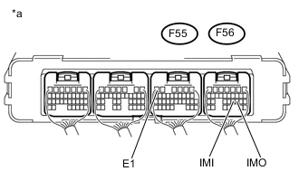
Text in Illustration *a Component with harness connected
(Power Management Control ECU)
Measure the voltage according to the value(s) in the table below.
-
Waveform 1
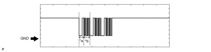
Text in Illustration *a Approximately 160 ms *b Approximately 270 ms Measurement Condition Item Content Tester Connection F56-20 (IMO) - F55-6 (E1) Tool Setting 2 V/DIV., 500 ms./DIV. Condition Within 3 seconds of hybrid control system start or within 3 seconds of power switch turned on (IG) after auxiliary battery cable disconnected and reconnected -
Waveform 2
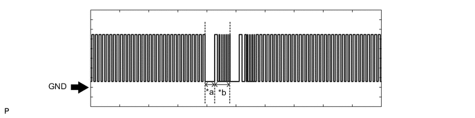
Text in Illustration *a Approximately 160 ms *b Approximately 270 ms Measurement Condition Item Content Tester Connection F56-21 (IMI) - F55-6 (E1) Tool Setting 2 V/DIV., 500 ms./DIV. Condition Within 3 seconds of hybrid control system start or within 3 seconds of power switch turned on (IG) after auxiliary battery cable disconnected and reconnected OK The waveform is displayed as shown in illustration.
-
NG
CHECK AND REPLACE HARNESS AND CONNECTOR (POWER MANAGEMENT CONTROL ECU - ID CODE BOX (IMMOBILISER CODE ECU)) Click here
OK
-
-
READ VALUE USING GTS (STARTER REQUEST SIGNAL)
-
Connect the GTS to the DLC3.
-
Turn the power switch on (IG).
-
Turn the GTS on.
-
Enter the following menus: Body Electrical / Power Source Control / Data List.
-
According to the display on the GTS, read the Data List.
Power Source Control Tester Display Measurement Item/Range Normal Condition Diagnostic Note Starter Request Signal Hybrid control system start request signal status/ON or OFF ON: With the shift lever in P and brake pedal depressed, the power switch is pressed and held
OFF: After approx. 1 sec. has elapsed, the power switch is released
-
When the hybrid control system cannot be started due to a start request signal malfunction, OFF is displayed.
-
When the power switch is pressed, the duration of time that ON is displayed will be extremely short. As such, the power switch needs to be pressed and held for a certain amount of time.
Note
Check that the entry indicator in the combination meter assembly illuminates in green, and then press the power switch.
OK The display changes in response to the operation of the power switch. -
OK
GO TO HYBRID CONTROL SYSTEM (HOW TO PROCEED WITH TROUBLESHOOTING) Click here
NG
REPLACE POWER MANAGEMENT CONTROL ECU Click here
-
-
INSPECT STOP LIGHT SWITCH ASSEMBLY
-
Inspect the stop light switch assembly Click here.
NG
REPLACE STOP LIGHT SWITCH ASSEMBLY Click here
OK
-
-
CHECK HARNESS AND CONNECTOR (STOP LIGHT SWITCH ASSEMBLY - POWER MANAGEMENT CONTROL ECU AND AUXILIARY BATTERY)
-
Disconnect the A23 stop light switch assembly connector.
-
Disconnect the A27 power management control ECU connector.
-
Measure the resistance according to the value(s) in the table below.
Standard Resistance Tester Connection Condition Specified Condition A27-23 (STP) - A23-1 Always Below 1 Ω A27-23 (STP) - Body ground Always 10 kΩ or higher -
Reconnect the A27 power management control ECU connector.
-
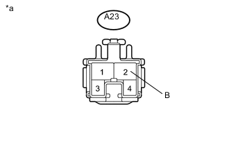
Text in Illustration *a Front view of wire harness connector
(to Stop Light Switch Assembly)
Measure the voltage according to the value(s) in the table below.
Standard Voltage Tester Connection Condition Specified Condition A23-2 - Body ground Always 11 to 14 V
OK
REPLACE POWER MANAGEMENT CONTROL ECU Click here
NG
REPAIR OR REPLACE HARNESS OR CONNECTOR
-
-
CHECK HARNESS AND CONNECTOR (STOP LIGHT SWITCH ASSEMBLY - POWER SOURCE AND BODY GROUND)
-
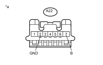
Text in Illustration *a Front view of wire harness connector
(to Stop Light Switch Assembly)
Disconnect the A22 stop light switch assembly connector.
-
Measure the voltage and resistance according to the value(s) in the table below.
Standard Voltage Tester Connection Switch Condition Specified Condition A22-7 (B) - A22-2 (GND) Power switch off 11 to 14 V Standard Resistance Tester Connection Condition Specified Condition A22-2 (GND) - Body ground Always Below 1 Ω
NG
REPAIR OR REPLACE HARNESS OR CONNECTOR
OK
-
-
CHECK STOP LIGHT SWITCH ASSEMBLY
-
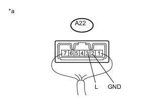
Text in Illustration *a Component with harness connected
(Stop Light Switch Assembly)
Reconnect the A22 stop light switch assembly connector.
-
Measure the voltage according to the value(s) in the table below.
Standard Voltage Tester Connection Switch Condition Specified Condition A22-3 (L) - A22-2 (GND) Power switch off, brake pedal not depressed Below 1 V A22-3 (L) - A22-2 (GND) Power switch off, brake pedal depressed 11 to 14 V
NG
REPLACE STOP LIGHT SWITCH ASSEMBLY Click here
OK
-
-
CHECK HARNESS AND CONNECTOR (POWER MANAGEMENT CONTROL ECU - STOP LIGHT SWITCH ASSEMBLY)
-
Disconnect the A22*1 or A23*2 stop light switch assembly connector.
-
*1: for LED Type Stop Light
-
*2: for Bulb Type Stop Light
-
-
Measure the resistance according to the value(s) in the table below.
Standard Resistance for LED Type Stop Light Tester Connection Condition Specified Condition A27-23 (STP) - A22-3 (L) Always Below 1 Ω A27-23 (STP) - Body ground Always 10 kΩ or higher for Bulb Type Stop Light Tester Connection Condition Specified Condition A27-23 (STP) - A23-1 (L) Always Below 1 Ω A27-23 (STP) - Body ground Always 10 kΩ or higher -
Reconnect the A22*1 or A23*2 stop light switch assembly connector.
-
*1: for LED Type Stop Light
-
*2: for Bulb Type Stop Light
-
-
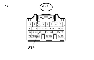
Text in Illustration *a Front view of wire harness connector
(to Power Management Control ECU)
Disconnect the A27 power management control ECU connector.
-
Measure the voltage according to the value(s) in the table below.
Standard Voltage Tester Connection Condition Specified Condition A27-23 (STP) - Body ground Brake pedal released 1 V or less Brake pedal depressed 9 V or higher
OK
REPLACE POWER MANAGEMENT CONTROL ECU Click here
NG
REPAIR OR REPLACE HARNESS OR CONNECTOR
-
-
REPLACE STEERING LOCK ECU (STEERING LOCK ACTUATOR ASSEMBLY)
-
Replace the steering lock ECU (steering lock actuator assembly) with a new one.
-
for LHD Click here
-
for RHD Click here
-
-
Perform the registration procedures (Refer to the Service Bulletin).
NEXT
-
-
CHECK HYBRID CONTROL SYSTEM (READY ON)
-
Place the electrical key transmitter sub-assembly on the driver seat.
-
Depress the brake pedal.
-
Confirm that the entry indicator in the combination meter assembly illuminates in green, and then press the power switch and check that the hybrid system turns on (READY).
OK Power source mode becomes on (READY).
OK
END (STEERING LOCK ECU (STEERING LOCK ACTUATOR ASSEMBLY) WAS DEFECTIVE)
NG
REPLACE ID CODE BOX (IMMOBILISER CODE ECU)
-
-
REPLACE CERTIFICATION ECU (SMART KEY ECU ASSEMBLY)
-
Replace the certification ECU (smart key ECU assembly) with a new one (Refer to the Service Bulletin).
-
Perform the registration procedures (Refer to the Service Bulletin).
NEXT
-
-
CHECK HYBRID CONTROL SYSTEM (READY ON)
-
Place the electrical key transmitter sub-assembly on the driver seat.
-
Depress the brake pedal.
-
Confirm that the entry indicator in the combination meter assembly illuminates in green, and then press the power switch and check that the hybrid system turns on (READY).
OK Power source mode becomes on (READY).
OK
END (CERTIFICATION ECU (SMART KEY ECU ASSEMBLY) WAS DEFECTIVE)
NG
REPLACE ID CODE BOX (IMMOBILISER CODE ECU)
-
-
CHECK AND REPLACE HARNESS AND CONNECTOR (POWER MANAGEMENT CONTROL ECU - ID CODE BOX (IMMOBILISER CODE ECU))
-
Disconnect the F56 power management control ECU connector.
-
Disconnect the F43 ID code box (immobiliser code ECU) connector.
-
Measure the resistance according to the value(s) in the table below.
Standard Resistance Tester Connection Condition Specified Condition F56-20 (IMO) - F43-3 (EFII) Always Below 1 Ω F56-21 (IMI) - F43-4 (EFIO) Always Below 1 Ω
NG
REPAIR OR REPLACE HARNESS OR CONNECTOR
OK
-
-
REPLACE POWER MANAGEMENT CONTROL ECU
-
Replace the power management control ECU with a new one Click here.
NEXT
-
-
CHECK HYBRID CONTROL SYSTEM (READY ON)
-
Place the electrical key transmitter sub-assembly on the driver seat.
-
Depress the brake pedal.
-
Confirm that the entry indicator in the combination meter assembly illuminates in green, and then press the power switch and check that the hybrid system turns on (READY).
OK Power source mode becomes on (READY).
OK
END (POWER MANAGEMENT CONTROL ECU WAS DEFECTIVE)
NG
REPLACE ID CODE BOX (IMMOBILISER CODE ECU)
-