ENTRY AND START SYSTEM(for Start Function), Diagnostic DTC:B2285
| DTC Code | DTC Name |
|---|---|
| B2285 | Steering Lock Position Signal Circuit Malfunction |
DESCRIPTION
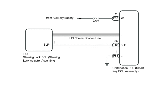
This DTC is stored when the steering lock position signal sent by the steering lock ECU via direct line and the steering lock position signal sent via LIN communication do not match.
Tech Tips
When the auxiliary battery cable is disconnected and reconnected, the power source returns to the mode it was in before the auxiliary battery cable was disconnected.
| DTC No. | DTC Detection Condition | Trouble Area | DTC Output Confirmation Operation |
|---|---|---|---|
| B2285 | The steering lock position signal sent by the steering lock ECU via direct line and the steering lock position signal sent via LIN communication (1-trip detection logic*) do not match. |
|
Disconnect the cable from the negative (-) auxiliary battery terminal, wait 30 seconds and reconnect the cable to the negative (-) auxiliary battery terminal. Wait another 40 seconds or more with the power switch off (steering locked), and then turn the power switch on (ACC) (steering unlocked) and wait 40 seconds or more. |
*: Only output while a malfunction is present and the power switch is on (IG)
| Vehicle Condition when Malfunction Detected | Fail-safe Function when Malfunction Detected |
|---|---|
| The hybrid control system cannot be started. | A hybrid control system start command is not output. |
| DTC No. | Data List Item | Active Test Item |
|---|---|---|
| B2285 |
Power Source Control
Entry & Start |
- |
WIRING DIAGRAM
CAUTION / NOTICE / HINT
Note
-
When using the GTS with the vehicle power switch off, connect the GTS to the vehicle and turn a courtesy light switch on and off at intervals of 1.5 seconds or less until communication between the GTS and the vehicle begins. Then select the Model Code "KEY REGIST" under manual mode and enter the following menus: Body Electrical / Entry & Start(CAN). While using the GTS, periodically turn a courtesy light switch on and off at intervals of 1.5 seconds or less to maintain communication between the GTS and the vehicle.
-
The entry and start system uses multiplex communication. First perform the inspections in "How to Proceed with Troubleshooting" to confirm that there are no communication malfunctions before proceeding with troubleshooting Click here.
-
Before replacing the certification ECU (smart key ECU assembly) or steering lock ECU (steering lock actuator assembly), refer to the entry and start system (for Entry Function) precaution Click here.
-
After performing repairs, perform the operation that fulfills the DTC output confirmation operation, and then confirm that no DTCs are output again.
-
Inspect the fuses of circuits related to this system before performing the following inspection procedure.
Tech Tips
If the entry indicator in the combination meter assembly blinks in green, the steering lock bar may be stuck.
PROCEDURE
-
CHECK FOR DTC (LIN COMMUNICATION SYSTEM)
-
Clear the DTCs Click here.
OK LIN communication system DTC B2785 is not output simultaneously. Tech Tips
-
If the steering wheel cannot be locked or unlocked, the power switch cannot be turned on (IG) and the hybrid control system cannot be started.
-
If LIN communication is not available, the steering wheel cannot be locked or unlocked.
-
NG 
GO TO LIN COMMUNICATION SYSTEM Click here
OK 
-
-
READ VALUE USING GTS (STEERING UNLOCK SWITCH)
-
Connect the GTS to the DLC3.
-
Turn the power switch on (IG).
-
Turn the GTS on.
-
Enter the following menus: Body Electrical / Power Source Control / Data List.
-
According to the display on the GTS, read the Data List.
Power Source Control Tester Display Measurement Item/Range Normal Condition Diagnostic Note Steering Unlock Switch State of steering unlock sensor signal output from steering lock actuator assembly / OFF or ON OFF: Steering locked
ON: Steering unlocked
-
When the shift lever is in P and the power switch is off, if any door is opened or closed, the steering is locked.
-
When the electrical key transmitter sub-assembly is inside the vehicle and the power switch is turned on (ACC) or on (IG), the steering unlocks.
-
The hybrid control system cannot be started when the steering unlock signal is off.
Result Result Proceed to Data List item does not change A Data List item changes (for LHD) B Data List item changes (for RHD) C -
B
REPLACE STEERING LOCK ECU (STEERING LOCK ACTUATOR ASSEMBLY) Click here
C
REPLACE STEERING LOCK ECU (STEERING LOCK ACTUATOR ASSEMBLY) Click here
A
-
-
CHECK HARNESS AND CONNECTOR (POWER SOURCE)
-
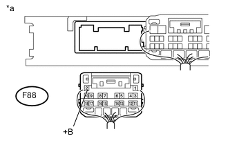
Text in Illustration *a Rear view of wire harness connector
(to Certification ECU (Smart Key ECU Assembly))
Disconnect the certification ECU (smart key ECU assembly) connector.
-
Measure the voltage according to the value(s) in the table below.
Standard Voltage Tester Connection Switch Condition Specified Condition F88-2 (+B) - Body ground Power switch off 11 to 14 V
NG
REPAIR OR REPLACE HARNESS OR CONNECTOR IN CIRCUIT CONNECTED TO POWER SOURCE
OK
-
-
CHECK HARNESS AND CONNECTOR (GROUND)
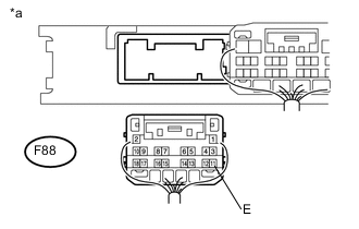
Text in Illustration *a Rear view of wire harness connector
(to Certification ECU (Smart Key ECU Assembly))
-
Measure the resistance according to the value(s) in the table below.
Standard Resistance Tester Connection Condition Specified Condition F88-11 (E) - Body ground Always Below 1 Ω
NG
REPAIR OR REPLACE HARNESS OR CONNECTOR
OK
-
-
INSPECT STEERING LOCK ECU (STEERING LOCK ACTUATOR ASSEMBLY)
-
Reconnect the steering lock ECU (steering lock actuator assembly) connector.
-
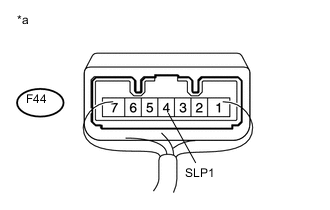
Text in Illustration *a Component with harness connected
(Steering Lock ECU (Steering Lock Actuator Assembly))
Measure the resistance according to the value(s) in the table below.
Standard Resistance Tester Connection Condition Specified Condition Positive (+) tester probe → F44-4 (SLP1)
Negative (-) tester probe → Body ground
Steering locked* 10 kΩ or higher Positive (+) tester probe → F44-4 (SLP1)
Negative (-) tester probe → Body ground
Steering unlocked* Below 1 Ω Tech Tips
-
*: If any of the doors are opened then closed with the shift lever in P and the power switch off, the steering wheel will be locked. If the power switch is then turned on (ACC) or on (IG), the steering wheel will be unlocked.
-
DTC B2285 may be stored due to a malfunction in the steering lock ECU (steering lock actuator assembly). The steering lock position signal and unlock position signal are sent from the steering lock ECU (steering lock actuator assembly) to the certification ECU (smart key ECU assembly) individually.
Result Result Proceed to OK A NG (for LHD) B NG (for RHD) C -
B
REPLACE STEERING LOCK ECU (STEERING LOCK ACTUATOR ASSEMBLY) Click here
C
REPLACE STEERING LOCK ECU (STEERING LOCK ACTUATOR ASSEMBLY) Click here
A
-
-
CHECK HARNESS AND CONNECTOR (CERTIFICATION ECU (SMART KEY ECU ASSEMBLY) - STEERING LOCK ECU (STEERING LOCK ACTUATOR ASSEMBLY))
-
Disconnect the F86 certification ECU (smart key ECU assembly) connector.
-
Disconnect the F44 steering lock ECU (steering lock actuator assembly) connector.
-
Measure the resistance according to the value(s) in the table below.
Standard Resistance Tester Connection Condition Specified Condition F86-26 (SLP) - F44-4 (SLP1) Always Below 1 Ω F86-26 (SLP) - Body ground Always 10 kΩ or higher
OK
REPLACE CERTIFICATION ECU (SMART KEY ECU ASSEMBLY)
NG
REPAIR OR REPLACE HARNESS OR CONNECTOR
-