STEERING LOCK SYSTEM, Diagnostic DTC:B2788
| DTC Code | DTC Name |
|---|---|
| B2788 | IG2 Signal Malfunction |
DESCRIPTION
This DTC is stored when the steering lock ECU (steering lock actuator assembly) detects an IG2 power supply malfunction.
Tech Tips
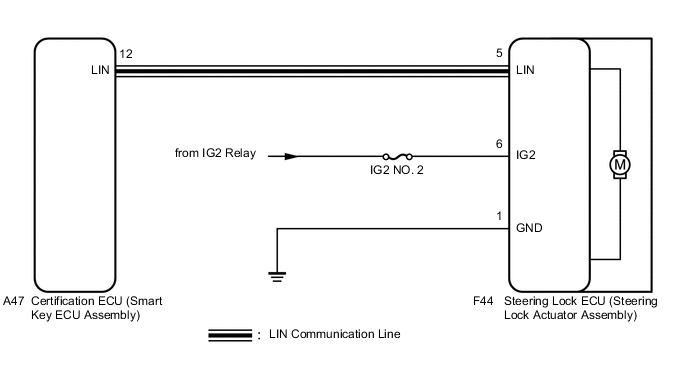
The steering lock ECU (steering lock actuator assembly) is not connected to the CAN communication system. However, the steering lock ECU (steering lock actuator assembly) is connected to the certification ECU (smart key ECU assembly) via LIN communication and communicates with other components via CAN communication through the certification ECU (smart key ECU assembly).
| DTC No. | Detection Condition | Trouble Area | DTC Output Confirmation Operation |
|---|---|---|---|
| B2788 | Mismatch between the steering lock ECU (steering lock actuator assembly) IG2 input from the LIN communication system and from the direct line (1-trip detection logic*). |
|
No confirmation operation is necessary (monitoring is continuous). |
-
*: Only output while a malfunction is present and the power switch is on (IG).
| Vehicle Condition when Malfunction Detected | Fail-safe Function when Malfunction Detected |
|---|---|
| The steering cannot be locked or unlocked. For this reason, the hybrid control system cannot be started. | - |
| DTC No. | Data List Item | Active Test Item |
|---|---|---|
| B2788 | - | - |
WIRING DIAGRAM
CAUTION / NOTICE / HINT
Note
-
When using the GTS with the vehicle power switch off, connect the GTS to the vehicle and turn a courtesy light switch on and off at intervals of 1.5 seconds or less until communication between the GTS and the vehicle begins. Then select the Model Code "KEY REGIST" under manual mode and enter the following menus: Body Electrical / Entry & Start(CAN). While using the GTS, periodically turn a courtesy light switch on and off at intervals of 1.5 seconds or less to maintain communication between the GTS and the vehicle.
-
The steering lock system uses LIN communication. First perform the inspections in "How to Proceed with Troubleshooting" to confirm that there are no communication malfunctions before proceeding with troubleshooting Click here.
-
Inspect the fuses for circuits related to this system before performing the following inspection procedure.
-
After performing repairs, confirm that no DTCs are output again Click here.
-
When replacing the steering lock ECU (steering lock actuator assembly), registration must be performed (refer to Service Bulletin).
PROCEDURE
-
INSPECT STEERING LOCK ECU (POWER SOURCE MODE SIGNAL)
-
Make sure that there is no looseness at the locking part and the connecting part of the connector.
-
Disconnect the steering lock ECU (steering lock actuator assembly) connector.
-
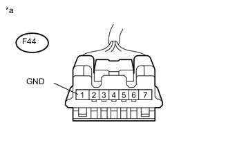
Text in Illustration *a Front view of wire harness connector
(to Steering Lock ECU (Steering Lock Actuator Assembly))
Measure the resistance according to the value(s) in the table below.
Standard Resistance Tester Connection Switch Condition Specified Condition F44-1 (GND) - Body ground Always Below 1 Ω -
Reconnect the steering lock ECU (steering lock actuator assembly) connector.
-
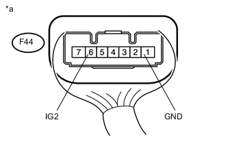
Text in Illustration *a Component with harness connected
(Steering Lock ECU (Steering Lock Actuator Assembly))
Measure the voltage according to the value(s) in the table below.
Standard Voltage Tester Connection Condition Specified Condition F44-6 (IG2) - F44-1 (GND) Power switch on (IG) 11 to 14 V F44-6 (IG2) - F44-1 (GND) Power switch off Below 1 V Result Result Proceed to NG A OK (for LHD) B OK (for RHD) C
A 
REPAIR OR REPLACE HARNESS OR CONNECTOR
B
REPLACE STEERING LOCK ACTUATOR ASSEMBLY Click here
C
REPLACE STEERING LOCK ACTUATOR ASSEMBLY Click here
-