POWER STEERING SYSTEM, Diagnostic DTC:C1524, C1555
| DTC Code | DTC Name |
|---|---|
| C1524 | Motor Circuit Malfunction |
| C1555 | Motor Relay Welding Failure |
DESCRIPTION
The power steering ECU assembly supplies the current to the power steering motor through the motor circuit.
| DTC No. | DTC Detection Condition | Trouble Area |
|---|---|---|
| C1524 | Short (or open) in motor circuit or abnormal voltage or current in motor circuit. |
|
| C1555 | Motor relay circuit malfunction. |
|
WIRING DIAGRAM
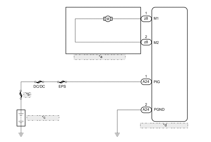
| *a | Power Steering Motor Assembly |
| *b | MAIN |
| *c | Auxiliary Battery |
| *d | Power Steering ECU Assembly |
CAUTION / NOTICE / HINT
Note
-
If the power steering ECU assembly has been replaced with a new one, perform assist map writing and torque sensor zero point calibration Click here.
-
Inspect the fuses for circuits related to this system before performing the following inspection procedure.
PROCEDURE
-
CHECK POWER STEERING ECU ASSEMBLY
-
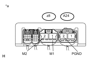
Text in Illustration *a Component with harness connected
(Power Steering ECU Assembly)
Turn the ignition switch to ON (IG).
-
Measure the voltage according to the value(s) in the table below.
Standard Voltage Tester Connection Condition Specified Condition z8-1 (M1) - A24-2 (PGND) Ignition switch ON (READY)
Turn steering wheel to right
9 to 16 V Ignition switch ON (READY)
Turn steering wheel to left
6 to 11 V z8-2 (M2) - A24-2 (PGND) Ignition switch ON (READY)
Turn steering wheel to right
6 to 11 V Ignition switch ON (READY)
Turn steering wheel to left
9 to 16 V
NG 
CHECK HARNESS AND CONNECTOR (POWER STEERING ECU ASSEMBLY - BATTERY AND BODY GROUND) Click here
OK 
-
-
INSPECT POWER STEERING MOTOR ASSEMBLY
-
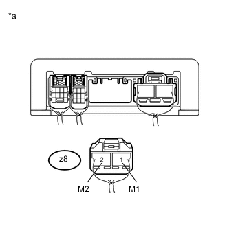
Text in Illustration *a Rear view of wire harness connector
(to Power Steering ECU Assembly)
Disconnect the power steering ECU assembly connector.
-
Measure the resistance according to the value(s) in the table below.
Standard Resistance Tester Connection Condition Specified Condition z8-1 (M1) - z8-2 (M2) Always 0.1 to 1.0 Ω z8-1 (M1) - Body ground Always 1 MΩ or higher z8-2 (M2) - Body ground Always 1 MΩ or higher Result Result Proceed to OK A NG (for LHD) B NG (for RHD) C
B 
REPLACE POWER STEERING MOTOR ASSEMBLY Click here
C
REPLACE POWER STEERING MOTOR ASSEMBLY Click here
A
-
-
CHECK HARNESS AND CONNECTOR (POWER STEERING ECU ASSEMBLY - BATTERY AND BODY GROUND)
-
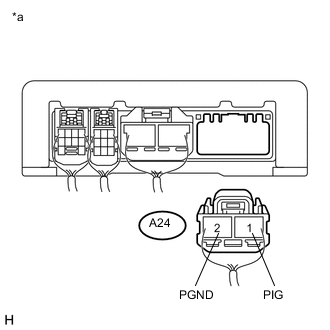
Text in Illustration *a Rear view of wire harness connector
(to Power Steering ECU Assembly)
Disconnect the power steering ECU assembly connector.
-
Measure the voltage according to the value(s) in the table below.
Standard Voltage Tester Connection Condition Specified Condition A24-1 (PIG) - Body ground Always 9 to 16 V -
Measure the resistance according to the value(s) in the table below.
Standard Resistance Tester Connection Condition Specified Condition A24-2 (PGND) - Body ground Always Below 1 Ω Result Result Proceed to NG A OK (for LHD) B OK (for RHD) C
A
REPAIR OR REPLACE HARNESS OR CONNECTOR
B
REPLACE POWER STEERING ECU ASSEMBLY Click here
C
REPLACE POWER STEERING ECU ASSEMBLY Click here
-