ELECTRONICALLY CONTROLLED BRAKE SYSTEM, Diagnostic DTC:C1247/47, C1346/71, C1392/48

| DTC Code | DTC Name |
|---|---|
| C1247/47 | Stroke Sensor Malfunction |
| C1346/71 | Stroke Sensor Zero Point Learning Malfunction (Test Mode DTC) |
| C1392/48 | Stroke Sensor Zero Point Calibration Undone |
DESCRIPTION
The brake pedal stroke sensor assembly sends a signal about the pedal stroke to the skid control ECU.
DTC C1346/71 will be cleared when the brake pedal stroke sensor assembly sends a brake pedal stroke sensor assembly signal or when Test Mode ends. DTC C1346/71 is output only in Test Mode.
| DTC No. | INF Code | DTC Detection Condition | Trouble Area |
|---|---|---|---|
| C1247/47 | 211 | Sensor supply voltage (VCM1) is 4.75 V or less, or 5.25 V or more for 0.2 seconds or more. |
|
| ↑ | 212 | Sensor output voltage 1 (SKS1) is less than 5.5%, or 94% or more (less than 0.27 V, or 4.7 V or more) of sensor supply voltage (VCM1) for 0.2 seconds or more. |
|
| ↑ | 213 | Sensor output voltage 2 (SKS2) is less than 5.5%, or 94% or more (less than 0.27 V, or 4.7 V or more) of sensor supply voltage (VCSK) for 0.2 seconds or more. | ↑ |
| ↑ | 214 | Either of the following is detected:
|
↑ |
| ↑ | 215 | Either of the following is detected:
|
↑ |
| ↑ | 218 | An excessive difference between the change in sensor output 1 (SKS1) and sensor output 2 (SKS2) is detected for 0.2 seconds or more. | ↑ |
| ↑ | 219 | Sensor data is invalid for 0.2 seconds or more. (Skid control ECU internal monitor circuit malfunction.) |
↑ |
| ↑ | 223 | Sensor data is invalid for 0.2 seconds or more. (Open, short, or noise.) |
↑ |
| C1392/48 | - | Zero point calibration of brake pedal stroke sensor assembly is unfinished. |
|
| C1346/71 | - | Detected only during Test Mode. |
|
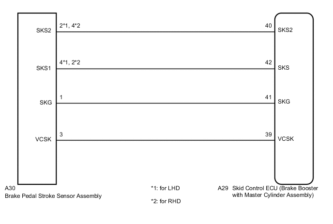
WIRING DIAGRAM
CAUTION / NOTICE / HINT
Note
When replacing the skid control ECU (brake booster with master cylinder assembly) or brake pedal stroke sensor assembly, perform initialization and calibration of the linear solenoid valve Click here.
Tech Tips
Check the condition of each related circuit connector before troubleshooting Click here.
PROCEDURE
-
CHECK BRAKE PEDAL
-
Check that the brake pedal and the brake pedal stroke sensor assembly are properly installed and that the pedal can be depressed normally.
-
Check and adjust the brake pedal height (See page for LHD or Click here for RHD).
-
Adjust the brake pedal stroke sensor assembly (See page for LHD or Click here for RHD).
NEXT 
-
-
CHECK HARNESS AND CONNECTOR (SKID CONTROL ECU - BRAKE PEDAL STROKE SENSOR ASSEMBLY)
-
Make sure that there is no looseness at the locking part and the connecting part of the connectors.
-
Disconnect the A29 skid control ECU (brake booster with master cylinder assembly) connector and the brake pedal stroke sensor assembly connector.
-
Check both the connector case and the terminal for deformation and corrosion.
OK No deformation or corrosion. -
Measure the resistance according to the value(s) in the table below.
Standard Resistance (for LHD) Tester Connection Condition Specified Condition A29-39 (VCSK) - A30-3 (VCSK) Always Below 1 Ω A29-39 (VCSK) - Body ground Always 10 kΩ or higher A29-41 (SKG) - A30-1 (SKG) Always Below 1 Ω A29-41 (SKG) - Body ground Always 10 kΩ or higher A29-42 (SKS) - A30-4 (SKS1) Always Below 1 Ω A29-42 (SKS) - Body ground Always 10 kΩ or higher A29-40 (SKS2) - A30-2 (SKS2) Always Below 1 Ω A29-40 (SKS2) - Body ground Always 10 kΩ or higher (for RHD) Tester Connection Condition Specified Condition A29-39 (VCSK) - A30-3 (VCSK) Always Below 1 Ω A29-39 (VCSK) - Body ground Always 10 kΩ or higher A29-41 (SKG) - A30-1 (SKG) Always Below 1 Ω A29-41 (SKG) - Body ground Always 10 kΩ or higher A29-42 (SKS) - A30-2 (SKS1) Always Below 1 Ω A29-42 (SKS) - Body ground Always 10 kΩ or higher A29-40 (SKS2) - A30-4 (SKS2) Always Below 1 Ω A29-40 (SKS2) - Body ground Always 10 kΩ or higher
NG 
REPAIR OR REPLACE HARNESS OR CONNECTOR
OK
-
-
INSPECT SKID CONTROL ECU (SENSOR OUTPUT)
-
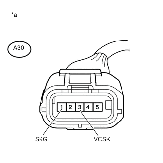
Text in Illustration *a Front view of wire harness connector
(to Brake Pedal Stroke Sensor Assembly)
Reconnect the skid control ECU (brake booster with master cylinder assembly) connector.
-
Turn the ignition switch to ON (IG).
-
Measure the voltage according to the value(s) in the table below.
Standard Voltage Tester Connection Switch Condition Specified Condition A30-3 (VCSK) - A30-1 (SKG) Ignition switch ON (IG) 4.84 to 5.16 V Result Result Proceed to OK (for LHD) A OK (for RHD) B NG (for LHD) C NG (for RHD) D
A
REPLACE BRAKE PEDAL STROKE SENSOR ASSEMBLY Click here
B
REPLACE BRAKE PEDAL STROKE SENSOR ASSEMBLY Click here
C
REPLACE BRAKE BOOSTER WITH MASTER CYLINDER ASSEMBLY Click here
D
REPLACE BRAKE BOOSTER WITH MASTER CYLINDER ASSEMBLY Click here
-