FUEL INJECTOR REMOVAL

CAUTION / NOTICE / HINT
Tech Tips
Perform "Inspection After Repair" after replacing the fuel injector assembly Click here.
PROCEDURE
-
PRECAUTION
Note
After turning the ignition switch off, waiting time may be required before disconnecting the cable from the negative (-) auxiliary battery terminal. Therefore, make sure to read the disconnecting the cable from the negative (-) auxiliary battery terminal notice before proceeding with work Click here.
-
DISCHARGE FUEL SYSTEM PRESSURE
-
REMOVE FRONT FLOOR COVER RH (for Front Floor Cover Type A)
-
REMOVE CENTER FRONT FLOOR COVER (for Front Floor Cover Type B)
-
REMOVE FRONT FLOOR COVER RH (for Front Floor Cover Type B)
-
DISCONNECT CABLE FROM NEGATIVE AUXILIARY BATTERY TERMINAL
Note
When disconnecting the cable, some systems need to be initialized after the cable is reconnected Click here.
-
REMOVE EGR VALVE WITH COOLER ASSEMBLY
-
SEPARATE BRAKE MASTER CYLINDER RESERVOIR ASSEMBLY (for RHD)
-
REMOVE NO. 2 CYLINDER HEAD COVER (w/ No. 2 Cylinder Head Cover)
-
REMOVE NO. 1 IGNITION COIL
-
SEPARATE ENGINE WIRE (for LHD)
-
SEPARATE ENGINE WIRE (for RHD)
-
REMOVE ENGINE COVER BRACKET
-
REMOVE CYLINDER HEAD COVER SUB-ASSEMBLY
-
REMOVE EFI FUEL PIPE CLAMP
-
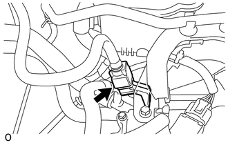
Remove the EFI fuel pipe clamp.
-
-
DISCONNECT FUEL TUBE SUB-ASSEMBLY
-
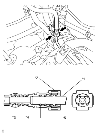
Text in Illustration *1 Fuel delivery pipe *2 Fuel Tube Connector *3 Nylon Tube *4 O-ring *5 Retainer 
Pinch 
Pull Pinch the retainer of the fuel tube connector, and then pull the fuel tube connector off of the fuel delivery pipe.
Note
-
Check for foreign matter on the fuel tube around the fuel tube connector. Clean it if necessary. Foreign matter can affect the ability of the O-ring to seal the fuel tube connector and fuel delivery pipe.
-
Do not use any tools to separate the fuel tube connector and fuel delivery.
-
Do not forcibly bend, kink or twist the nylon tube.
-
Keep the fuel tube connector and fuel delivery pipe free from foreign matter.
-
If the fuel tube connector and fuel delivery pipe are stuck, push and pull to release them.
-
Put the fuel tube connector and fuel delivery pipe in plastic bags to prevent damage and contamination.
-
-
-
REMOVE FUEL DELIVERY PIPE
-
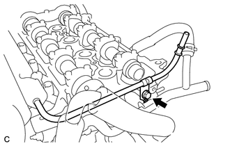
Remove the bolt.
-
Disengage the clamp to disconnect the wire harness.
-
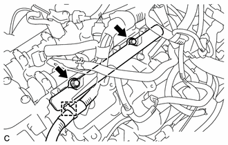
Remove the 2 bolts and the fuel delivery pipe with the 4 fuel injectors.
Note
Be careful not to drop the fuel injectors when removing the fuel delivery pipe.
-
-
REMOVE FUEL DELIVERY SPACER
-
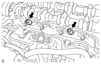
Remove the 2 fuel delivery spacers from the cylinder head.
-
-
REMOVE INJECTOR VIBRATION INSULATOR
-
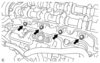
Remove the 4 injector vibration insulators from the cylinder head.
-
-
REMOVE FUEL INJECTOR ASSEMBLY
-
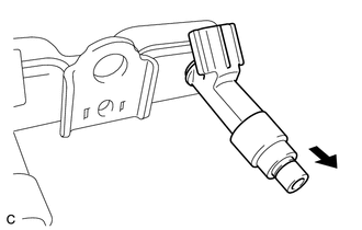
Pull the 4 fuel injector assemblies out of the fuel delivery pipe.
Text in Illustration Pull -
Remove the O-ring from each fuel injector.
-
For reinstallation, attach a tag or label to each injector shaft.
Note
Prevent entry of foreign matter by covering the fuel injectors with plastic bags.
-