CENTER AIRBAG SENSOR ASSEMBLY INSTALLATION

-
INSTALL CENTER AIRBAG SENSOR ASSEMBLY
-
Check that the power switch is off.
-
Check that the cable is disconnected from the negative (-) battery terminal.
CAUTION:
Wait at least 90 seconds after disconnecting the cable from the negative (-) battery terminal to disable the SRS system.
-
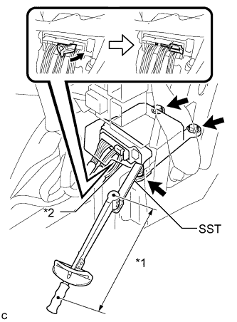
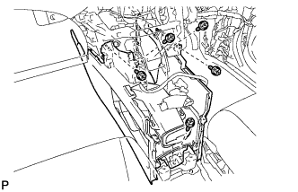
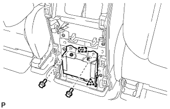
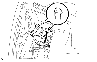
Text in Illustration *1 Fulcrum Length *2 Waterproof Sheet Using SST and a torque wrench, install the center airbag sensor assembly with the 3 bolts.
- SST
- 09961-00950
- Torque:
- without SST
- 18 N*m { 178 kgf*cm, 13 ft.*lbf }
- with SST
- 11 N*m { 112 kgf*cm, 8 ft.*lbf }
Note
-
Use a torque wrench with a fulcrum length of 250 mm (9.84 in.).
-
This torque value is effective when SST is parallel to a torque wrench.
-
If the center airbag sensor assembly has been dropped, or there are any cracks, dents or other defects in the case or connector, replace it with a new one.
-
When installing the center airbag sensor assembly, be careful that the SRS wiring does not interfere with or is not pinched between other parts.
-
When the power switch is first turned on (IG) after the center airbag sensor assembly has been replaced, make sure that no one is in the vehicle.
-
Connect the connector to the center airbag sensor assembly as shown in the illustration.
Note
When connecting any airbag connector, take care not to damage the airbag wire harness.
-
Check that the waterproof sheet is properly set.
-
Check that there is no looseness in the installation parts of the center airbag sensor assembly.
-
-
INSTALL CONSOLE BOX (for LHD)
-
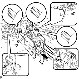
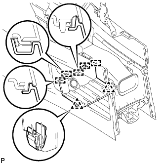
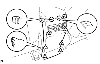
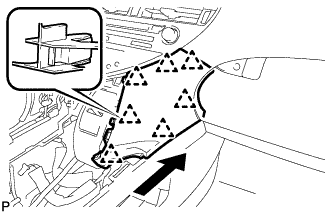
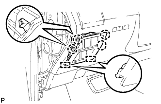
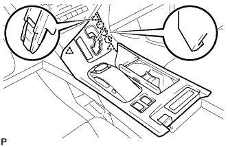
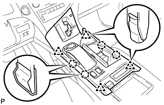
Text in Illustration *1 Clamp *2 Guide Engage the 3 guides as shown in the illustration.
-
Engage the 2 clamps.
-
Install the 3 clips.
-
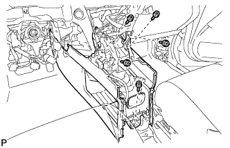
Install the console box with the 5 screws <D>.
-
-
INSTALL CONSOLE BOX (for RHD)
-
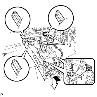
Text in Illustration *1 Clamp *2 Guide Engage the 3 guides as shown in the illustration.
-
Engage the 2 clamps.
-
Install the 2 clips.
-
Install the console box with the 5 screws <D>.
-
-
INSTALL FRONT CONSOLE BOX COVER
-
Connect the connector.
-
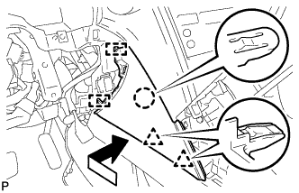
Engage the 5 guides and 2 clips, and install the front console box cover.
-
-
INSTALL REAR CONSOLE BOX ASSEMBLY
-
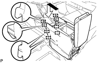
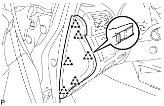
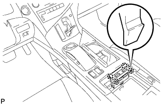
Engage the 8 guides as shown in the illustration.
-
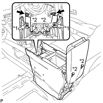
Text in Illustration *1 Screw *2 Bolt Install the rear console box assembly with the 2 screws and 4 bolts.
-
Connect each connector.
-
-
INSTALL MULTI-MEDIA INTERFACE ECU ASSEMBLY
-
Connect the connector.
-
Engage the clip and guide.
-
Install the multi-media interface ECU assembly with the 2 bolts.
- Torque:
- 6.0 N*m { 61 kgf*cm, 53 in.*lbf }
-
-
INSTALL CONSOLE REAR END PANEL SUB-ASSEMBLY
-
w/o Rear Seat Entertainment System:
-
Engage the 4 claws and 6 clips to install the console rear end panel sub-assembly.
-
-
w/ Rear Seat Entertainment System:
-
Connect each connector.
-
Engage the 4 claws and 6 clips to install the console rear end panel sub-assembly.
-
-
-
INSTALL LOWER INSTRUMENT PANEL FINISH PANEL
-
Engage the 7 clips to install the lower instrument panel finish panel as shown in the illustration.
-
-
INSTALL INSTRUMENT PANEL FINISH PANEL
-
Engage the 2 guides, claw and 2 clips to install the instrument panel finish panel as shown in the illustration.
-
-
INSTALL LOWER INSTRUMENT PANEL FINISH PANEL SUB-ASSEMBLY
-
Connect each connector.
-

Engage the 8 clips and 2 guides.
-
Install the lower instrument panel finish panel sub-assembly with the 2 screws <D>.
-
Engage the 2 claws to close the cover as shown in the illustration.
-
-
INSTALL NO. 1 SWITCH HOLE BASE
-
Connect each connector.
-
Engage the 4 claws and 2 guides to install the No. 1 switch hole base.
-
-
INSTALL INSTRUMENT PANEL GARNISH LH
-
Engage the 6 clips to install the instrument panel garnish LH.
-
-
INSTALL NO. 2 CONSOLE BOX DUCT
-
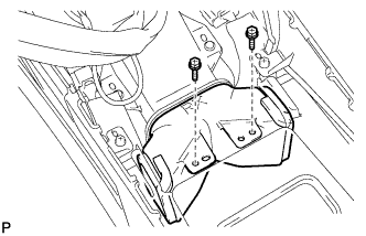
Install the No. 2 console box duct with the 2 screws.
-
-
INSTALL UPPER CONSOLE PANEL SUB-ASSEMBLY
-
Engage the clamp.
-
Connect each connector.
-
Engage the 3 claws and 3 clips.
-
w/o Seat Heater System:
-
Connect the connector to the console box hole cover.
-
-
w/ Seat Heater System:
-
Connect the connector.
-
Engage the 4 claws to install the seat heater switch assembly.
-
-
Engage the 4 claws and 4 clips to install the upper console panel sub-assembly.
-
-
INSTALL SHIFT LEVER KNOB SUB-ASSEMBLY
-
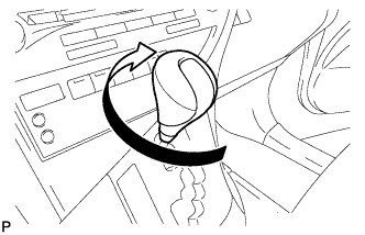
Turn the shift lever knob sub-assembly clockwise to install the shift lever knob sub-assembly.
-
-
CONNECT CABLE TO NEGATIVE BATTERY TERMINAL
Note
When disconnecting the cable, some systems need to be initialized after the cable is reconnected Click here.
-
INSTALL REAR DECK FLOOR BOX
-

Install the rear deck floor box with the 3 clips.
-
-
PERFORM DIAGNOSTIC SYSTEM CHECK
-
Perform a diagnostic system check Click here.
-
-
INSPECT SRS WARNING LIGHT
-
Inspect the SRS warning light Click here.
-
-
INSPECT SUSPENSION CONTROL SYSTEM
-
Inspect the suspension control system Click here.
-