THEFT DETERRENT SYSTEM (w/ Intrusion Sensor), Diagnostic DTC:B2769

| DTC Code | DTC Name |
|---|---|
| B2769 | Tilt Sensor Signal Circuit Malfunction |
DESCRIPTION
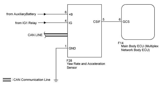
The yaw rate and acceleration sensor conducts self-diagnosis immediately after power is supplied to the sensor (when the theft deterrent system is set).
If a malfunction is detected in the CSIF-GCS line, the main body ECU (multiplex network body ECU) stores this DTC.
| DTC No. | DTC Detection Condition | Trouble Area |
|---|---|---|
| B2769 | After normal/trouble signal is output from yaw rate and acceleration sensor as result of self-diagnosis, following malfunctions are detected:
|
|
WIRING DIAGRAM
INSPECTION PROCEDURE
Note
When replacing the yaw rate and acceleration sensor, perform zero point calibration Click here.
PROCEDURE
-
CHECK HARNESS AND CONNECTOR (MAIN BODY ECU - YAW RATE AND ACCELERATION SENSOR)
-
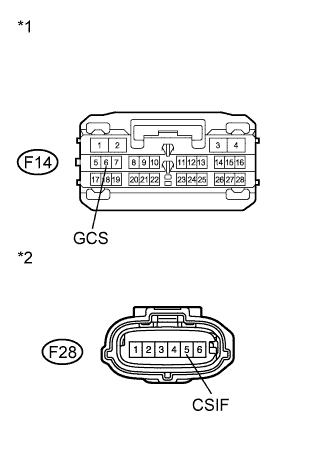
Text in Illustration *1 Front view of wire harness connector
(to Main Body ECU (Multiplex Network Body ECU))
*2 Front view of wire harness connector
(to Yaw Rate and Acceleration Sensor)
Disconnect the F14 main body ECU (multiplex network body ECU) and F28 yaw rate and acceleration sensor connectors.
-
Measure the resistance according to the value(s) in the table below.
Standard Resistance Tester Connection Condition Specified Condition F14-6 (GCS) - F28-5 (CSIF) Always Below 1 Ω F14-6 (GCS) - Body ground Always 10 kΩ or higher
NG 
REPAIR OR REPLACE HARNESS OR CONNECTOR
OK 
-
-
REPLACE YAW RATE AND ACCELERATION SENSOR
-
Replace the yaw rate and acceleration sensor Click here.
NEXT
-
-
CHECK FOR DTC
-
Clear the DTCs Click here.
-
Turn the power switch on (IG), then off.
-
Set the theft deterrent system to the "ARMED STATE".
-
Check that the security indicator changes from illuminated to flashing.
-
Set the theft deterrent system to the "DISARMED STATE".
-
Check for DTCs Click here.
OK DTC B2769 is not output.
NG
REPLACE MAIN BODY ECU (MULTIPLEX NETWORK BODY ECU) Click here
OK 
END (YAW RATE AND ACCELERATION SENSOR WAS FAULTY)
-