ENTRY AND START SYSTEM (for Start Function) Power Source Mode does not Change to ON (IG and ACC)
DESCRIPTION
When the power switch is pushed with the electrical key in the cabin, the power management control ECU receives signals to change the power source mode.
Tech Tips
To allow use of the intelligent tester to inspect the push-button start function when the power source mode is off, repeat opening and closing any of the doors. Opening and closing a door establishes communication between the intelligent tester and the power management control ECU. (Opening and closing a door can also be simulated by operating a door courtesy light switch.)
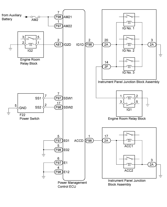
WIRING DIAGRAM
INSPECTION PROCEDURE
PROCEDURE
-
CHECK HARNESS AND CONNECTOR (AUXILIARY BATTERY - POWER MANAGEMENT CONTROL ECU)
-
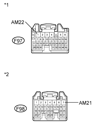
Text in Illustration *1 Front view of wire harness connector
(to Power Management Control ECU)
*2 Front view of wire harness connector
(to Power Management Control ECU)
Disconnect the F97 and F98 connectors from the power management control ECU.
-
Measure the voltage according to the value(s) in the table below.
Standard Voltage Tester Connection Condition Specified Condition F97-1 (AM22) - Body ground Always 9.5 to 16 V F98-7 (AM21) - Body ground Always 9.5 to 16 V
NG 
REPAIR OR REPLACE HARNESS OR CONNECTOR (AUXILIARY BATTERY - POWER MANAGEMENT CONTROL ECU)
OK 
-
-
CHECK HARNESS AND CONNECTOR (POWER MANAGEMENT CONTROL ECU - BODY GROUND)
-
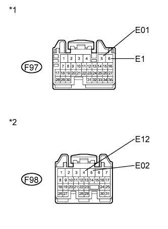
Text in Illustration *1 Front view of wire harness connector
(to Power Management Control ECU)
*2 Front view of wire harness connector
(to Power Management Control ECU)
Measure the resistance according to the value(s) in the table below.
Standard Resistance Tester Connection Condition Specified Condition F97-5 (E01) - Body ground Always Below 1 Ω F97-6 (E1) - Body ground Always Below 1 Ω F98-4 (E12) - Body ground Always Below 1 Ω F98-5 (E02) - Body ground Always Below 1 Ω
NG
REPAIR OR REPLACE HARNESS OR CONNECTOR (POWER MANAGEMENT CONTROL ECU - BODY GROUND)
OK
-
-
READ VALUE USING INTELLIGENT TESTER
-
Reconnect the F97 and F98 connectors to the power management control ECU.
-
Turn the power switch off.
-
Connect the intelligent tester to the DLC3.
-
Turn the power switch on (IG).
-
Turn the intelligent tester on.
-
Enter the following menus: Body / Power Source Control / Data List.
-
Read the Data List according to the display on the intelligent tester.
Power Source Control Tester Display Measurement Item/Range Normal Condition Diagnostic Note Key Certification Waiting Timed Out Key certification error detection/ No or Yes No: Key certification error not detected
Yes: Steering lock/unlock error detected
- OK When more than 1 second elapses after the power switch is turned from off to on (IG), NO is displayed in the Data List.
NG 
CHECK FOR DTC Click here
OK
-
-
READ VALUE USING INTELLIGENT TESTER
-
Read the Data List according to the display on the intelligent tester.
Power Source Control Tester Display Measurement Item/Range Normal Condition Diagnostic Note Start Switch1 Start switch 1/ON or OFF ON: Power switch pushed
OFF: Power switch not pushed
- Start Switch2 Start switch 2/ON or OFF ON: Power switch pushed
OFF: Power switch not pushed
- OK ON (power switch is pushed) and OFF (power switch is not pushed) appear on the screen.
NG
CHECK POWER SWITCH Click here
OK
-
-
CHECK POWER MANAGEMENT CONTROL ECU
-
Read the Data List according to the display on the intelligent tester.
Power Source Control Tester Display Measurement Item/Range Normal Condition Diagnostic Note Power Supply Condition Power supply condition/All OFF, ACC ON, IG1 ON, IG2 ON, ST ON ALL OFF: All relays off
ACC ON: ACC relay on
IG1 ON: IG1 relay on
IG2 ON: IG2 relay on
ST ON: ST request signal on
- -
Measure the voltage while checking the Data List on the intelligent tester.
Standard Voltage Tester Connection Condition Specified Condition F98-2 (IG1D) - Body ground Power switch off Below 1 V F98-2 (IG1D) - Body ground Power switch on (ACC) Below 1 V F98-2 (IG1D) - Body ground Power switch on (IG) Output voltage at terminal AM21 or AM22 -2.5 V or more A81-2 (IG2D) - Body ground Power switch off Below 1 V A81-2 (IG2D) - Body ground Power switch on (ACC) Below 1 V A81-2 (IG2D) - Body ground Power switch on (IG) Output voltage at terminal AM21 or AM22 -2.5 V or more F98-1 (ACCD) - Body ground Power switch off Below 1 V F98-1 (ACCD) - Body ground Power switch on (IG) Output voltage at terminal AM21 or AM22 -2.5 V or more F98-1 (ACCD) - Body ground Power switch on (ACC) Output voltage at terminal AM21 or AM22 -2.5 V or more
-
Proceed to the next step based on inspection result.
Result Result Proceed to OK A NG (for LHD) B NG (for RHD) C
-
B
REPLACE POWER MANAGEMENT CONTROL ECU (for LHD) Click here
C
REPLACE POWER MANAGEMENT CONTROL ECU (for RHD) Click here
A
-
-
CONFIRMATION TEST
-
Check that the power source mode becomes on (ACC) and on (IG) when the power switch is operated.
OK Power source mode becomes on (ACC) and on (IG) when the power switch is operated.
NG
CHECK RELAY CONTACT SIDE CIRCUIT
OK 
USE SIMULATION METHOD TO CHECK Click here
-
-
CHECK POWER SWITCH
-
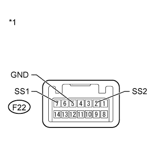
Text in Illustration *1 Component without harness connected
(Power Switch)
Remove the power switch Click here.
-
Measure the resistance according to the value(s) in the table below.
Standard Resistance Tester Connection Condition Specified Condition F22-7 (SS1) - F22-5 (GND) Pushed Below 1 Ω F22-7 (SS1) - F22-5 (GND) Not pushed 10 kΩ or higher F22-2 (SS2) - F22-5 (GND) Pushed Below 1 Ω F22-2 (SS2) - F22-5 (GND) Not pushed 10 kΩ or higher
NG
REPLACE POWER SWITCH Click here
OK
-
-
CHECK HARNESS AND CONNECTOR (POWER SWITCH - POWER MANAGEMENT CONTROL ECU AND BODY GROUND)
-
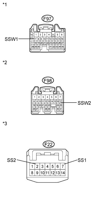
Text in Illustration *1 Front view of wire harness connector
(to Power Management Control ECU)
*2 Front view of wire harness connector
(to Power Management Control ECU)
*3 Front view of wire harness connector
(to Power Switch)
Disconnect the F97 and F98 connectors from the power management control ECU.
-
Measure the resistance according to the value(s) in the table below.
Standard Resistance Tester Connection Condition Specified Condition F98-17 (SSW2) - F22-2 (SS2) Always Below 1 Ω F97-7 (SSW1) - F22-7 (SS1) Always Below 1 Ω F98-17 (SSW2) - Body ground Always 10 kΩ or higher F97-7 (SSW1) - Body ground Always 10 kΩ or higher -
Proceed to the next step based on inspection result.
Result Result Proceed to NG A OK (for LHD) B OK (for RHD) C
B
REPLACE POWER MANAGEMENT CONTROL ECU (for LHD) Click here
C
REPLACE POWER MANAGEMENT CONTROL ECU (for RHD) Click here
A
REPAIR OR REPLACE HARNESS OR CONNECTOR (POWER SWITCH - POWER MANAGEMENT CONTROL ECU OR BODY GROUND)
-
-
CHECK FOR DTC
-
Enter the following menus: Body / Power Source Control and Entry & Start / DTC.
-
Check for DTCs.
Result Result Proceed to The following DTCs are not output:
-
B2785
-
B2287
-
B2784
A DTC B2785 is not output but DTC B2287 is output B DTCs other than B2287 are output. C -
B
GO TO OTHER FLOW CHART (Room Oscillator does not Recognize Key) Click here
C
GO TO OTHER FLOW CHART (DTC B2287)
A
GO TO DIAGNOSTIC TROUBLE CODE CHART
-