LIN COMMUNICATION SYSTEM, Diagnostic DTC:B2785

| DTC Code | DTC Name |
|---|---|
| B2785 | Communication Malfunction between ECUs Connected by LIN |
DESCRIPTION
The certification ECU (smart key ECU assembly) monitors communication between all the ECUs connected to the certification bus lines. When the certification ECU (smart key ECU assembly) detects errors in communication with all the ECUs connected to the certification bus lines at a set interval and 3 times in a row, DTC B2785 will be stored.
| DTC No. | DTC Detection Condition | Trouble Area |
|---|---|---|
| B2785 |
|
|
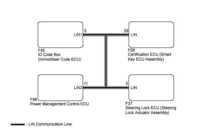
WIRING DIAGRAM
INSPECTION PROCEDURE
Note
-
If the certification ECU (smart key ECU assembly) is replaced, register the key.
-
If the steering lock ECU (steering lock actuator assembly) is replaced, register the ECU code.
-
If the ID code box (immobiliser code ECU) is replaced, register the ECU code and ECU communication ID.
-
When using the intelligent tester to troubleshoot with the power switch off:
Connect the intelligent tester to the DLC3, and turn the courtesy switch on and off at 1.5-second intervals until communication between the intelligent tester and vehicle begins.
PROCEDURE
-
CHECK HARNESS AND CONNECTOR (CERTIFICATION ECU - EACH ECU)
-
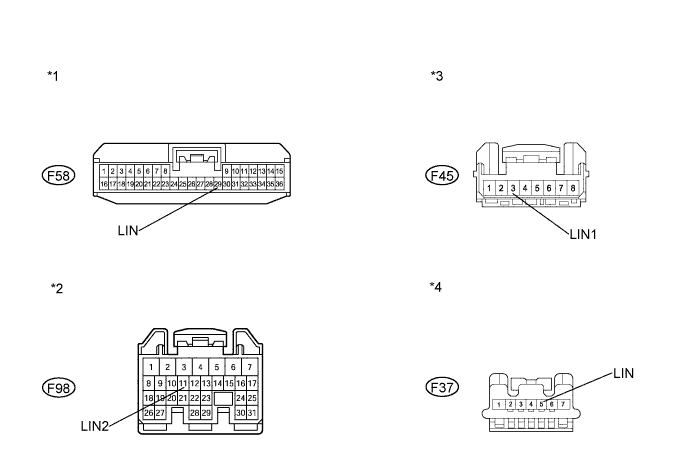
Disconnect the F58, F98, F45 and F37 connectors.
-
Measure the resistance according to the value(s) in the table below.
Standard Resistance Tester Connection Condition Specified Condition F58-29 (LIN) - F37-5 (LIN) Always Below 1 Ω F58-29 (LIN) - F98-11 (LIN2) Always Below 1 Ω F58-29 (LIN) - F45-3 (LIN1) Always Below 1 Ω F58-29 (LIN) - Body ground Always 10 kΩ or higher Text in Illustration *1 Front view of wire harness connector
(to Certification ECU (Smart Key ECU Assembly))
*2 Front view of wire harness connector
(to Power Management Control ECU)
*3 Front view of wire harness connector
(to ID code box (Immobiliser Code ECU))
*4 Front view of wire harness connector
(to Steering Lock ECU (Steering Lock Actuator Assembly))
NG 
REPAIR OR REPLACE HARNESS OR CONNECTOR
OK 
-
-
CHECK DTC OUTPUT (STEERING LOCK ECU (STEERING LOCK ACTUATOR ASSEMBLY))
-
Reconnect the F58, F98 and F45 connectors.
-
Clear the DTC Click here.
-
Recheck for DTCs.
Result Result Proceed to DTC B2785 is output A DTC B2785 is not output B
B
REPLACE STEERING LOCK ECU (STEERING LOCK ACTUATOR ASSEMBLY) Click here
A
-
-
CHECK DTC OUTPUT (POWER MANAGEMENT CONTROL ECU)
-
Reconnect the F37 connector.
-
Disconnect the F98 connector.
-
Clear the DTC Click here.
-
Recheck for DTCs.
Result Result Proceed to DTC B2785 is output A DTC B2785 is not output (for LHD) B DTC B2785 is not output (for RHD) C
B
REPLACE POWER MANAGEMENT CONTROL ECU (for LHD) Click here
C
REPLACE POWER MANAGEMENT CONTROL ECU (for RHD) Click here
A
-
-
CHECK DTC OUTPUT (ID CODE BOX (IMMOBILISER CODE ECU))
-
Reconnect the F98 connector.
-
Disconnect the F45 connector.
-
Clear the DTC Click here.
-
Recheck for DTCs.
Result Result Proceed to DTC B2785 is output A DTC B2785 is not output B
B
REPLACE ID CODE BOX (IMMOBILISER CODE ECU)
A 
REPLACE CERTIFICATION ECU (SMART KEY ECU ASSEMBLY)
-