STEREO COMPONENT AMPLIFIER INSTALLATION

-
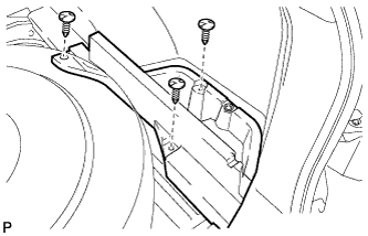
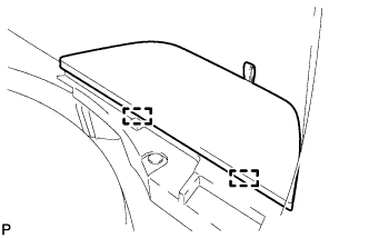
INSTALL NO. 1 AMPLIFIER BRACKET
-
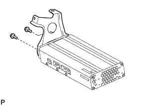
Install the No. 1 amplifier bracket with the 2 bolts.
- Torque:
- 4.8 N*m { 49 kgf*cm, 43 in.*lbf }
-
-
INSTALL NO. 2 AMPLIFIER BRACKET
-
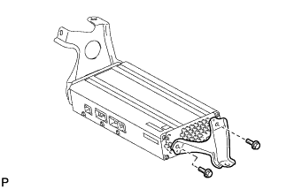
Install the No. 2 amplifier bracket with the 2 bolts.
- Torque:
- 4.8 N*m { 49 kgf*cm, 43 in.*lbf }
-
-
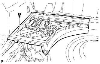
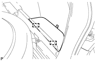
INSTALL STEREO COMPONENT AMPLIFIER ASSEMBLY WITH BRACKET
-
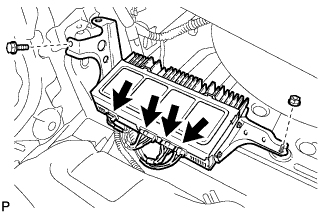
Install the stereo component amplifier assembly with bracket with the bolt and nut.
- Torque:
- 7.5 N*m { 77 kgf*cm, 66 in.*lbf }
-
Connect the 4 connectors.
-
-
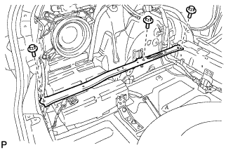
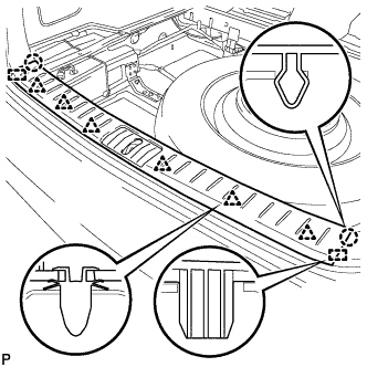
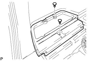
INSTALL REAR SEAT SUB FLOOR PANEL ASSEMBLY
-
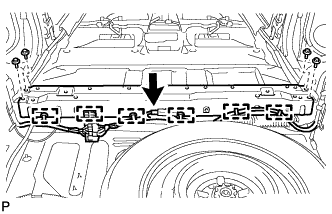
Install the rear seat sub floor panel assembly with the 4 bolts.
- Torque:
- 20 N*m { 204 kgf*cm, 15 ft.*lbf }
-
Engage the 6 clamps to install the wire harness.
-
Connect the connector.
-
-
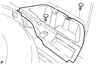
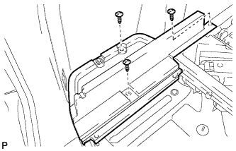
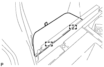
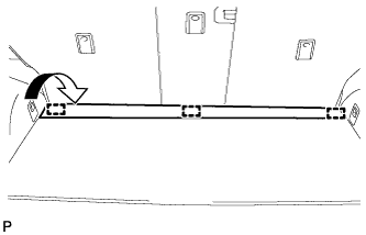
INSTALL NO. 2 DECK BOARD REINFORCEMENT
-
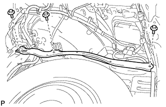
Install the No. 2 deck board reinforcement with the 3 bolts.
- Torque:
- 20 N*m { 204 kgf*cm, 15 ft.*lbf }
-
-
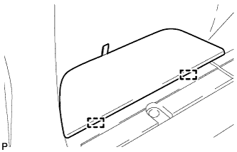
INSTALL NO. 1 DECK BOARD REINFORCEMENT
-
Install the No. 1 deck board reinforcement with the 3 bolts.
- Torque:
- 20 N*m { 204 kgf*cm, 15 ft.*lbf }
-
-
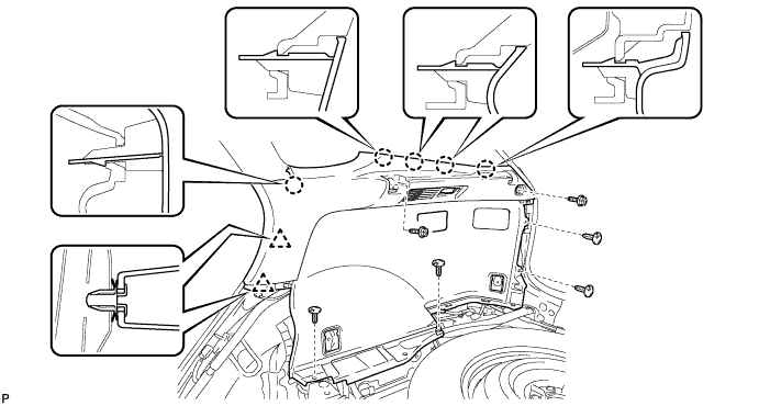
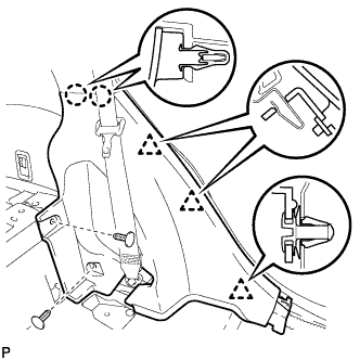
INSTALL DECK TRIM SIDE PANEL ASSEMBLY RH
-
Connect the connector.
-
Engage the 2 clips and the 5 claws.
-
Install the deck trim side panel assembly RH with the 2 bolts and 5 clips.
-
-
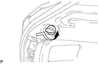
INSTALL HEIGHT CONTROL SWITCH (w/ Air Suspension)
-
Connect the connector.
-
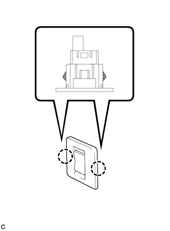
Engage the 2 claws to install the height control switch to the deck trim side panel assembly RH.
-
-
INSTALL RECLINING REMOTE CONTROL BEZEL RH
Tech Tips
Use the same procedure for the RH side and the LH side Click here.
-
INSTALL ROPE HOOK ASSEMBLY (for RH Side)
Tech Tips
Use the same procedure for the RH side and the LH side Click here.
-
INSTALL NO. 1 LUGGAGE COMPARTMENT TRIM HOOK (for RH Side)
-
Install the No. 1 luggage compartment trim hook as shown in the illustration.
-
-
INSTALL REAR SEAT SIDE COVER RH
Tech Tips
Use the same procedure for the RH side and the LH side Click here.
-
INSTALL REAR DOOR SCUFF PLATE RH
Tech Tips
Use the same procedure for the RH side and the LH side Click here.
-
INSTALL REAR SEAT ASSEMBLY RH
Tech Tips
Refer to the procedure from Install Rear Seat Assembly RH Click here.
-
INSTALL REAR FLOOR FINISH SIDE PLATE RH
Tech Tips
Use the same procedure for the RH side and the LH side Click here.
-
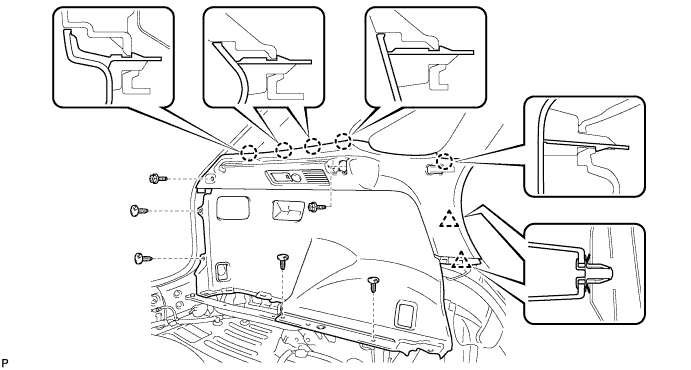
INSTALL DECK TRIM SIDE PANEL ASSEMBLY LH
-
Connect each connector.
-
Engage the 2 clips and the 5 claws.
-
Install the deck trim side panel assembly LH with the 2 bolts and 4 clips.
-
-
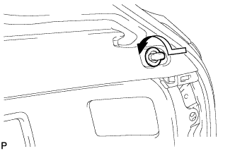
INSTALL RECLINING REMOTE CONTROL BEZEL LH
-
Engage the 4 claws and install the reclining remote control bezel LH.
-
-
INSTALL ROPE HOOK ASSEMBLY (for LH Side)
-
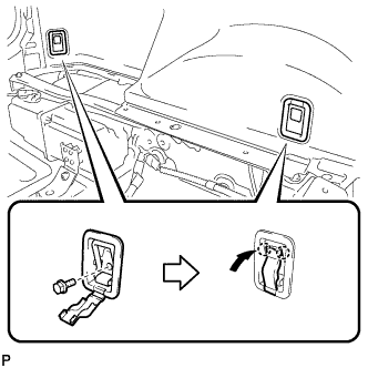
Install the 2 rope hook assemblies with the 2 bolts.
-
Engage the 2 claws.
-
-
INSTALL NO. 1 LUGGAGE COMPARTMENT TRIM HOOK (for LH Side)
-
Install the No. 1 luggage compartment trim hook as shown in the illustration.
-
-
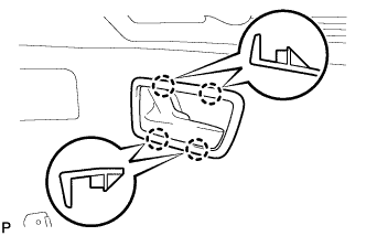
INSTALL REAR SEAT SIDE COVER LH
-
Engage the 2 claws and 3 clips.
-
Install the rear seat side cover LH with the 2 clips.
-
-
INSTALL REAR DOOR SCUFF PLATE LH
-
Engage the 3 clips, guide and 6 claws, and install the rear door scuff plate LH.
-
-
INSTALL REAR SEAT ASSEMBLY LH
Tech Tips
Refer to the procedure from Install Rear Seat Assembly LH Click here.
-
INSTALL REAR FLOOR FINISH SIDE PLATE LH
-
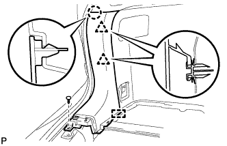
Engage the guide.
-
Engage the claw and 2 clips.
-
Install the rear floor finish side plate LH with the clip.
-
-
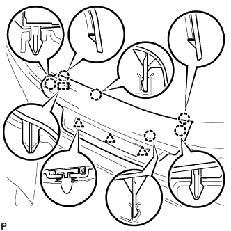
INSTALL REAR FLOOR FINISH PLATE
-
Engage the 6 clips, 2 claws and 2 guides, and install the rear floor finish plate.
-
-
INSTALL FRONT DECK FLOOR BOX
-
Install the front deck floor box with the clip.
-
-
INSTALL DECK SIDE TRIM BOX RH (for Full Size Spare Tire)
-
Install the deck side trim box RH with the 3 clips.
-
-
INSTALL DECK SIDE TRIM BOX RH (for Compact Spare Tire)
-
Install the deck side trim box RH with the 2 clips.
-
-
INSTALL DECK SIDE TRIM BOX LH (for Full Size Spare Tire)
-
Install the deck side trim box LH with the 3 clips.
-
-
INSTALL DECK SIDE TRIM BOX LH (for Compact Spare Tire)
-
Install the deck side trim box LH with the 2 clips.
-
-
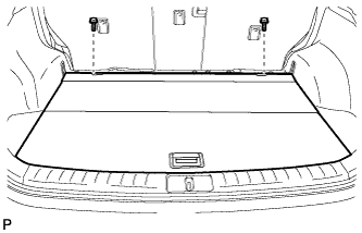
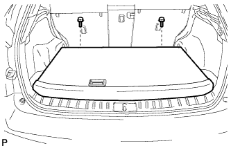
INSTALL TONNEAU COVER ASSEMBLY
-
Install the tonneau cover assembly.
-
-
INSTALL NO. 3 REAR FLOOR BOARD (for Full Size Spare Tire)
-
Engage the 2 guides and install the No. 3 rear floor board.
-
-
INSTALL NO. 3 REAR FLOOR BOARD (for Compact Spare Tire)
-
Engage the 2 guides and install the No. 3 rear floor board.
-
-
INSTALL NO. 4 REAR FLOOR BOARD (for Full Size Spare Tire)
-
Engage the 2 guides and install the No. 4 rear floor board.
-
-
INSTALL NO. 4 REAR FLOOR BOARD (for Compact Spare Tire)
-
Engage the 2 guides and install the No. 4 rear floor board.
-
-
INSTALL SPARE WHEEL COVER ASSEMBLY (for Compact Spare Tire)
-
Install the spare wheel cover assembly.
-
-
INSTALL DECK BOARD SUB-ASSEMBLY
-
for Compact Spare Tire:
-
Install the deck board sub-assembly with the 2 bolts.
-
-
for Full Size Spare Tire:
-
Install the deck board sub-assembly with the 2 bolts.
-
-
Engage the 3 fasteners as shown in the illustration.
-
-
INSTALL REAR DECK FLOOR BOX (w/ Navigation System for HDD)
-

Install the rear deck floor box with the 3 clips.
-
-
CONNECT CABLE TO NEGATIVE BATTERY TERMINAL
Note
When disconnecting the cable, some systems need to be initialized after the cable is reconnected Click here.
-
INSPECT SUSPENSION CONTROL SYSTEM
-
Inspect the suspension control system Click here.
-
-
INSPECT SRS WARNING LIGHT
-
Inspect SRS warning light Click here.
-