INSTRUMENT PANEL SAFETY PAD INSTALLATION

-
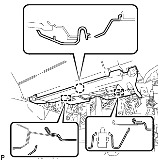
INSTALL NO. 3 INSTRUMENT PANEL STAY
-
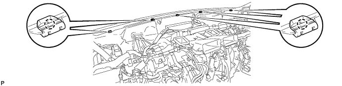
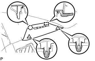
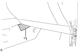
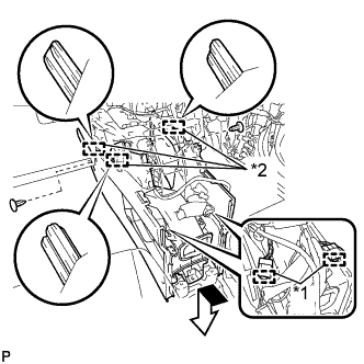
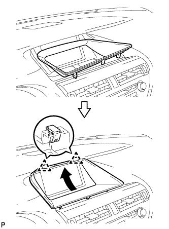
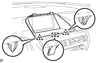
Engage the 5 claws to install the 5 No. 3 instrument panel stays.
-
-
INSTALL INSTRUMENT PANEL SAFETY PAD ASSEMBLY
-
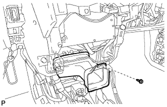
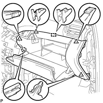
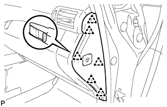
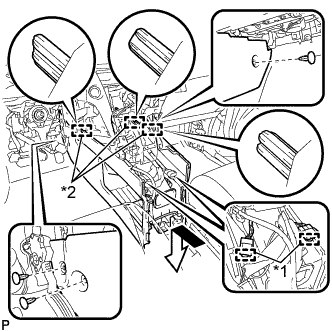
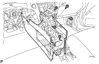
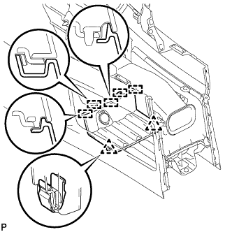
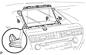
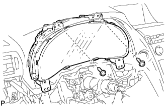
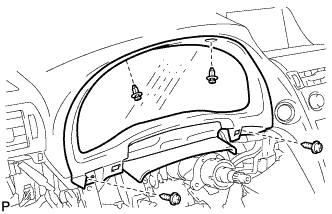
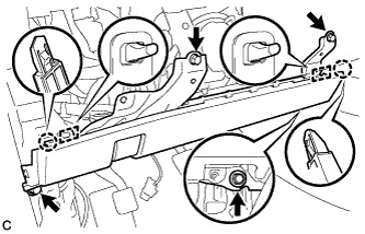
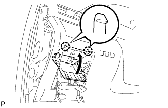
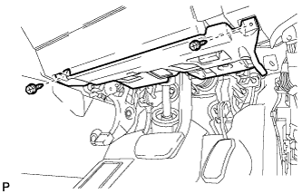
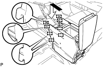
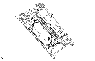
Engage the 5 claws and temporarily install the instrument panel safety pad assembly as shown in the illustration.
CAUTION:
Leaks of cold air may result in condensation in the instrument panel. This condensation may cause short circuits in electrical parts. Be sure to insert and fit the No. 1 heater to register duct and the No. 4 heater to register duct tightly to the No. 1 air duct sub-assembly.
Note
-
Do not damage the instrument panel safety pad assembly.
-
Do not allow the wire harnesses to interfere with the surrounding parts.
-
-
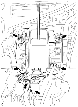
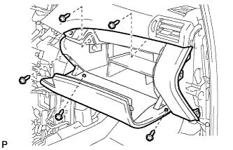
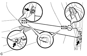
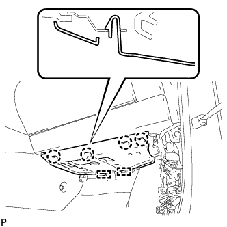
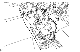
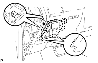
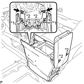
Install the 2 clips.
-
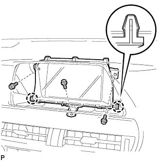
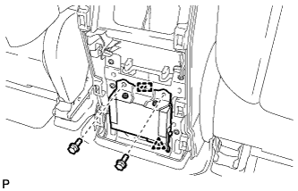
Install the 6 bolts <C> and nut <H> or <I>.
-
Install the 2 passenger airbag bolts <A> or <B>.
- Torque:
- 20 N*m { 204 kgf*cm, 15 ft.*lbf }
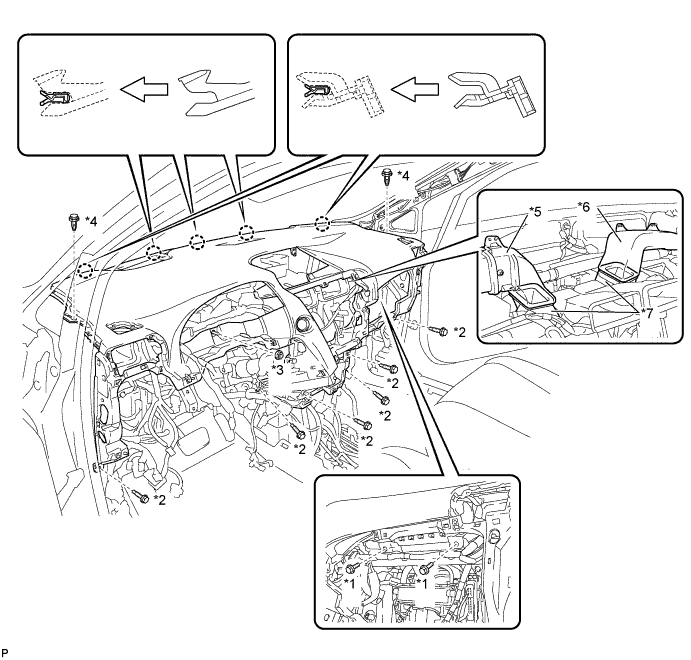
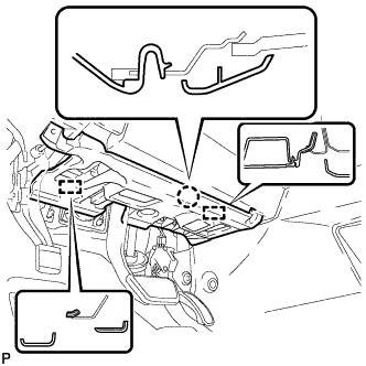
Text in Illustration *1 Passenger Airbag Bolt <A> or <B> *2 Bolt <C> *3 Nut <H> or <I> *4 Clip *5 No. 1 Heater To Register Duct *6 No. 4 Heater To Register Duct *7 No. 1 Air Duct Sub-assembly - - -
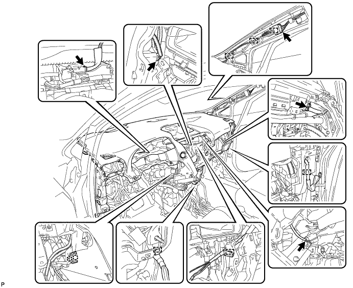
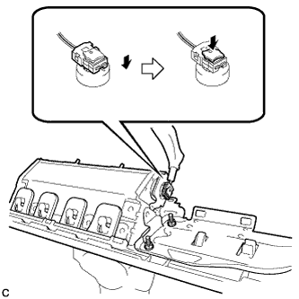
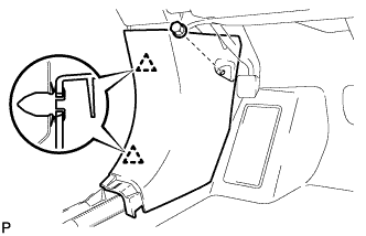
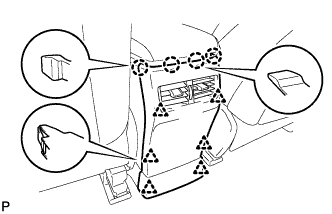
Engage the 2 claws to connect the room temperature sensor.
-
Engage each clamp.
-
Connect each connector.
-
-
CONNECT INSTRUMENT PANEL WIRE ASSEMBLY
-
Check that the power switch is off.
-
Check that the cable is disconnected from the negative (-) battery terminal.
CAUTION:
Wait at least 90 seconds after disconnecting the cable from the negative (-) battery terminal to disable the SRS system.
-
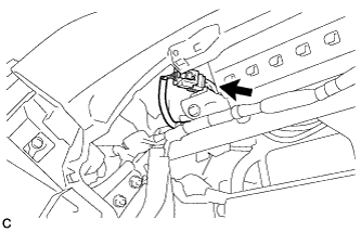
Connect the connector.
Note
When connecting any airbag connector, take care not to damage the airbag wire harness.
-
-
INSTALL NO. 1 CONSOLE BOX DUCT
-
Install the No. 1 console box duct with the screw <D>.
-
-
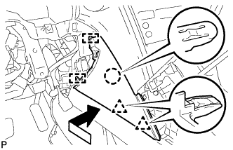
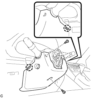
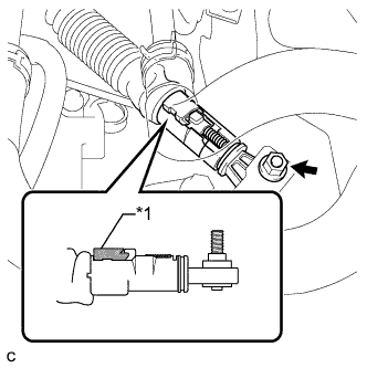
INSTALL SHIFT LEVER ASSEMBLY
Note
Check that the park/neutral position switch and the shift lever are in neutral.
-
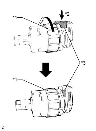
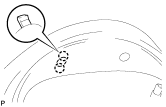
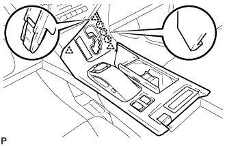
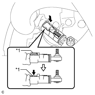
Text in Illustration *1 Lock Nut *2 Push in *3 Stopper Turn the lock nut of the transmission control cable counterclockwise. While holding the lock nut, push in the stopper.
-
Connect the outer part of the transmission control cable to the shift lever retainer.
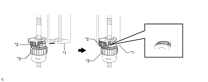
Text in Illustration *1 Shift Lever Retainer *2 Stopper *3 Lock Nut - - Note
The lock nut is fully seated against the shift lever retainer.
-
Install the transmission control cable end to the shift lever assembly.
Note
-
Install the floor shift cable with the uneven surface facing up.
-
Install the cable end all the way to the base of the pin.
-
-
Install the shift lever assembly with the 4 nuts.
- Torque:
- 12 N*m { 122 kgf*cm, 9 ft.*lbf }
-
Connect the 3 clamps to the shift lever assembly.
-
Connect the 2 connectors.
-
-
INSTALL NO. 1 DEFROSTER NOZZLE GARNISH
-
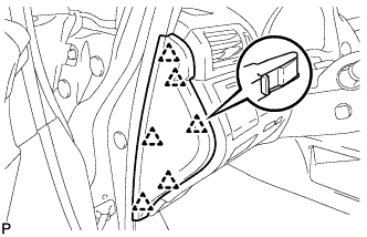
Engage the 2 claws to install the automatic light control sensor to the No. 1 defroster nozzle garnish.
-
Connect the connector.
-
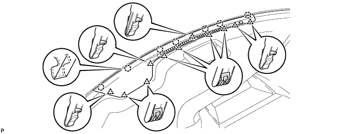
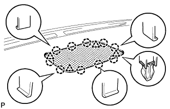
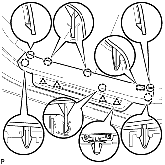
Engage the 7 claws and 11 clips to the No. 1 defroster nozzle garnish.
-
-
INSTALL FRONT NO. 4 SPEAKER ASSEMBLY
-
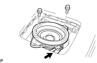
Connect the connector.
-
Install the front No. 4 speaker assembly with the 2 bolts.
- Torque:
- 7.5 N*m { 77 kgf*cm, 66 in.*lbf }
-
-
INSTALL NO. 1 SPEAKER OPENING COVER ASSEMBLY
-
Engage the 10 claws and 4 clips to install the No. 1 speaker opening cover assembly.
-
-
INSTALL NO. 1 INSTRUMENT PANEL REGISTER ASSEMBLY
-
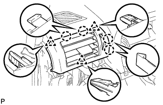
Engage the 4 claws and 3 clips to install the No. 1 instrument panel register assembly.
-
-
INSTALL NO. 2 INSTRUMENT PANEL REGISTER ASSEMBLY
Tech Tips
Use the same procedure as for the No. 1 instrument panel register assembly.
-
INSTALL FRONT PILLAR GARNISH LH
-
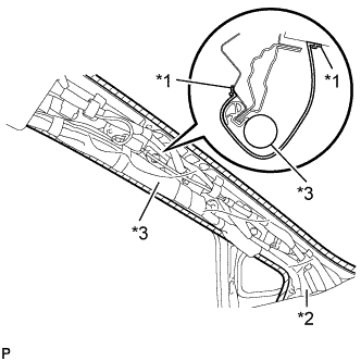
Text in Illustration *1 Adhesive Tape *2 Protective Cover *3 Curtain Shield Airbag Assembly Remove the protective cover.
-
Make sure that the front pillar garnish clip is not damaged.
Note
-
If there is any damage, replace the garnish clip with a new one.
-
When a garnish clip is being replaced, make sure to install it in the direction shown in the illustration.
-
-
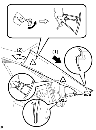
Engage the 2 guides.
-
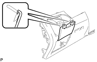
Turn the end of the front pillar garnish clip 90° with needle-nosed pliers and install it to the front pillar garnish LH.
Tech Tips
Tape the tips of the needle-nosed pliers before use.
-
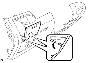
Engage the 2 clips to install the front pillar garnish LH.
-
-
INSTALL INSTRUMENT SIDE PANEL LH
-
Engage the guide.
-
Engage the 2 clips.
-
Engage the claw to install the instrument side panel LH.
-
-
INSTALL FRONT PILLAR GARNISH RH
Tech Tips
Use the same procedure as for the LH side Click here.
-
INSTALL INSTRUMENT SIDE PANEL RH
Tech Tips
Use the same procedure as for the LH side Click here.
-
INSTALL GLOVE COMPARTMENT DOOR ASSEMBLY
-
Connect each connector.
-
Engage the claw, 4 clips and guide.
-
Install the glove compartment door assembly with the 5 screws <F>.
-
-
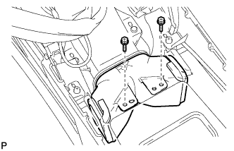
INSTALL FRONT PASSENGER SIDE KNEE AIRBAG ASSEMBLY
-
Check that the power switch is off.
-
Check that the cable is disconnected from the negative (-) battery terminal.
CAUTION:
Wait at least 90 seconds after disconnecting the cable from the negative (-) battery terminal to disable the SRS system.
-
Connect the airbag connector to the front passenger side knee airbag assembly.
Note
When connecting any airbag connector, take care not to damage the airbag wire harness.
-
Temporarily install the front passenger side knee airbag assembly with the claw and 2 pins.
-
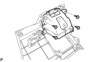
Install the front passenger side knee airbag assembly with the 3 bolts.
- Torque:
- 10 N*m { 102 kgf*cm, 7 ft.*lbf }
Note
Confirm that the front passenger side knee airbag assembly is installed securely without any excessive gaps and is not protruding outward.
-
Text in Illustration *1 Protective Tape Remove the protective tape.
-
-
INSTALL INSTRUMENT PANEL GARNISH RH (w/o Airbag Cut Off Switch)
Tech Tips
Use the same procedure as for the LH side.
-
INSTALL INSTRUMENT PANEL GARNISH RH (w/ Airbag Cut Off Switch)
-
Connect the connector.
-
Engage the 6 clips to install the instrument panel garnish RH.
-
-
INSTALL NO. 2 INSTRUMENT PANEL UNDER COVER SUB-ASSEMBLY
-
Connect the connector.
-
Engage the 2 guides and 4 claw to install the No. 2 instrument panel under cover sub-assembly.
-
-
INSTALL COWL SIDE TRIM SUB-ASSEMBLY RH
Tech Tips
Use the same procedure as for the LH side Click here.
-
INSTALL FRONT DOOR SCUFF PLATE RH
Tech Tips
Use the same procedure as for the LH side Click here.
-
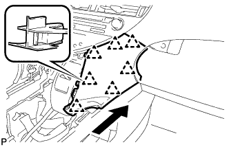
INSTALL CONSOLE BOX (for LHD)
-
Text in Illustration *1 Clamp *2 Guide Engage the 3 guides as shown in the illustration.
-
Engage the 2 clamps.
-
Install the 3 clips.
-
Install the console box with the 5 screws <D>.
-
-
INSTALL CONSOLE BOX (for RHD)
-
Text in Illustration *1 Clamp *2 Guide Engage the 3 guides as shown in the illustration.
-
Engage the 2 clamps.
-
Install the 2 clips.
-
Install the console box with the 5 screws <D>.
-
-
INSTALL FRONT CONSOLE BOX COVER
-
Connect the connector.
-
Engage the 5 guides and 2 clips, and install the front console box cover.
-
-
INSTALL RADIO RECEIVER ASSEMBLY WITH REGISTER
-
Connect each connector.
-
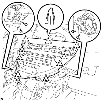
Engage the 9 clips.
-
Install the radio receiver assembly with register with the 4 bolts.
- Torque:
- 4.9 N*m { 50 kgf*cm, 43 in.*lbf }
-
-
INSTALL LOWER INSTRUMENT PANEL FINISH PANEL
-
Engage the 7 clips to install the lower instrument panel finish panel as shown in the illustration.
-
-
INSTALL INSTRUMENT PANEL FINISH PANEL
-
Engage the 2 guides, claw and 2 clips to install the instrument panel finish panel as shown in the illustration.
-
-
INSTALL MULTI-DISPLAY ASSEMBLY (w/ Navigation System)
-
Engage the 2 claws.
-
Install the multi-display assembly with the 3 bolts.
-
-
INSTALL ACCESSORY METER ASSEMBLY (w/o Navigation System)
-
Connect each connector.
-
Engage the 2 clips.
-
Install the accessory meter assembly with the 3 screws.
-
-
INSTALL CENTER INSTRUMENT CLUSTER FINISH PANEL
-
Engage the 2 clips as shown in the illustration.
-
Engage the 2 clips and guide to install the center instrument cluster finish panel.
-
-
INSTALL COMBINATION METER ASSEMBLY
-
Connect each connector.
-
Install the combination meter assembly with the 2 screws <G>.
-
-
INSTALL NO. 1 INSTRUMENT CLUSTER FINISH PANEL
-
Install the 2 screws <E>.
-
Install the No. 1 instrument cluster finish panel with the 2 clips.
-
-
INSTALL NO. 1 INSTRUMENT PANEL HOLE COVER
-
Engage the 2 claws to install the No. 1 instrument panel hole cover.
-
-
INSTALL NO. 2 INSTRUMENT PANEL HOLE COVER
Tech Tips
Use the same procedure as for the No. 1 instrument panel hole cover.
-
INSTALL DRIVER SIDE KNEE AIRBAG ASSEMBLY
-
Check that the power switch is off.
-
Check that the cable is disconnected from the negative (-) battery terminal.
CAUTION:
Wait at least 90 seconds after disconnecting the cable from the negative (-) battery terminal to disable the SRS system.
-
Engage the claw to connect the hood lock control cable to the driver side knee airbag assembly.
-
Connect the airbag connector to the driver side knee airbag assembly.
Note
When connecting any airbag connector, take care not to damage the airbag wire harness.
-
Temporarily install the driver side knee airbag assembly with the 2 claws and 2 hooks.
-
Install the driver side knee airbag assembly with the 4 bolts.
- Torque:
- 10 N*m { 102 kgf*cm, 7 ft.*lbf }
Note
Confirm that the driver side knee airbag assembly is installed securely without any excessive gaps and is not protruding outward.
-
-
INSTALL INSTRUMENT PANEL CUP HOLDER SUB-ASSEMBLY
-
Install the instrument panel cup holder sub-assembly with the 4 screws <F>.
-
-
INSTALL INSTRUMENT PANEL CUP HOLDER OUTER CASE
-
Open the cup holder.
-
Engage the 2 claws.
-
Engage the 2 claws to install the instrument panel cup holder outer outer case as shown in the illustration.
-
-
INSTALL LOWER INSTRUMENT PANEL FINISH PANEL SUB-ASSEMBLY
-
Connect each connector.
-

Engage the 8 clips and 2 guides.
-
Install the lower instrument panel finish panel sub-assembly with the 2 screws <D>.
-
Engage the 2 claws to close the cover as shown in the illustration.
-
-
INSTALL NO. 1 SWITCH HOLE BASE
-
Connect each connector.
-
Engage the 4 claws and 2 guides to install the No. 1 switch hole base.
-
-
INSTALL INSTRUMENT PANEL GARNISH LH
-
Engage the 6 clips to install the instrument panel garnish LH.
-
-
INSTALL NO. 1 INSTRUMENT PANEL UNDER COVER SUB-ASSEMBLY (for LHD)
-
Engage each clamp.
-
Connect each connector.
-
Engage the claw and 2 guides.
-

Install the No. 1 instrument panel under cover sub- assembly with the 2 screws <D>.
-
-
INSTALL NO. 1 INSTRUMENT PANEL UNDER COVER SUB-ASSEMBLY (for RHD)
-
Engage each clamp.
-
Connect each connector.
-
Engage the claw and 2 guides.
-
Install the No. 1 instrument panel under cover sub- assembly with the 2 screws <D>.
-
-
INSTALL COWL SIDE TRIM SUB-ASSEMBLY LH
-
Engage the 2 clips to install the cowl side trim sub-assembly LH.
-
Install the clip.
-
-
INSTALL FRONT DOOR SCUFF PLATE LH
-
w/ Illumination:
-
Connect the connector.
-
-
Engage the 4 clips, guide and 7 claws, and install the front door scuff plate LH.
-
-
INSTALL REAR CONSOLE BOX ASSEMBLY
-
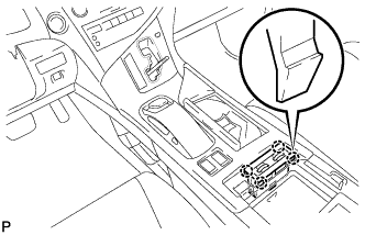
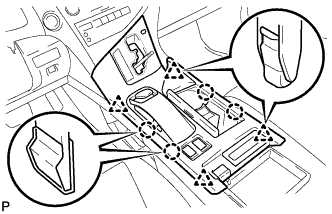
Engage the 8 guides as shown in the illustration.
-
Text in Illustration *1 Screw *2 Bolt Install the rear console box assembly with the 2 screws and 4 bolts.
-
Connect each connector.
-
-
INSTALL MULTI-MEDIA INTERFACE ECU ASSEMBLY
-
Connect the connector.
-
Engage the clip and guide.
-
Install the multi-media interface ECU assembly with the 2 bolts.
- Torque:
- 6.0 N*m { 61 kgf*cm, 53 in.*lbf }
-
-
INSTALL CONSOLE REAR END PANEL SUB-ASSEMBLY
-
w/o Rear Seat Entertainment System:
-
Engage the 4 claws and 6 clips to install the console rear end panel sub-assembly.
-
-
w/ Rear Seat Entertainment System:
-
Connect each connector.
-
Engage the 4 claws and 6 clips to install the console rear end panel sub-assembly.
-
-
-
INSTALL NO. 2 CONSOLE BOX DUCT
-
Install the No. 2 console box duct with the 2 screws.
-
-
INSTALL CONSOLE CUP HOLDER BOX
-
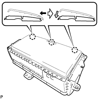
Engage the 3 claws as shown in the illustration.
-
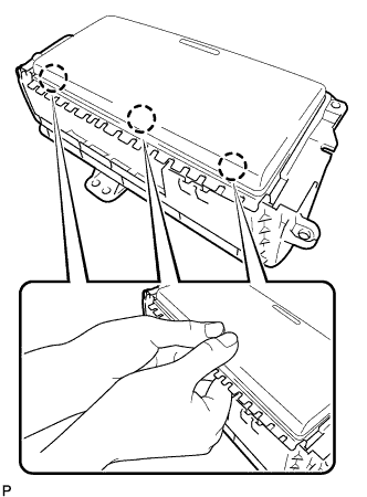
Engage the 3 claws as shown in the illustration to install the console cup holder box door to the console cup holder box.
-
-
INSTALL CONSOLE BOX CUP HOLDER
-
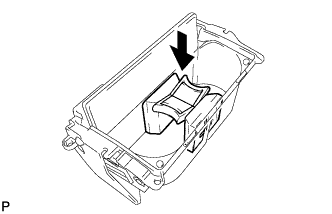
tall the console box cup holder to the console cup holder box sub-assembly as shown in the illustration.
-
-
INSTALL CONSOLE CUP HOLDER BOX SUB-ASSEMBLY
-
Install the console cup holder box sub-assembly with the 5 screws <F>.
-
-
INSTALL UPPER CONSOLE PANEL SUB-ASSEMBLY
-
Engage the clamp.
-
Connect each connector.
-
Engage the 3 claws and 3 clips.
-
w/o Seat Heater System:
-
Connect the connector to the console box hole cover.
-
-
w/ Seat Heater System:
-
Connect the connector.
-
Engage the 4 claws to install the seat heater switch assembly.
-
-
Engage the 4 claws and 4 clips to install the upper console panel sub-assembly.
-
-
INSTALL SHIFT LEVER KNOB SUB-ASSEMBLY
-
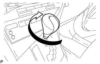
Turn the shift lever knob sub-assembly clockwise to install the shift lever knob sub-assembly.
-
-
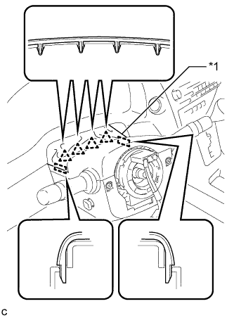
INSTALL TURN SIGNAL SWITCH ASSEMBLY WITH SPIRAL CABLE SUB-ASSEMBLY
-
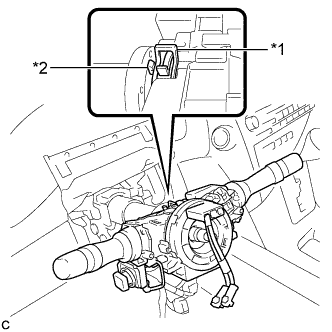
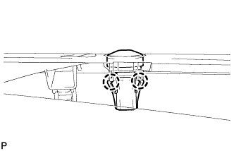
Text in Illustration *1 Clamp *2 Claw Using pliers, expand the clamp.
-
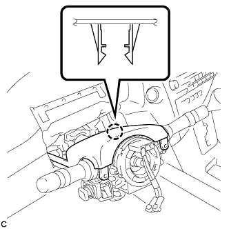
While holding the clamp expanded, install the turn signal switch assembly with spiral cable sub-assembly to the steering column assembly and engage the claw.
-
Return the clamp to its original position.
-
Connect the connectors to the turn signal switch assembly with spiral cable sub-assembly.
-
-
INSTALL STEERING COLUMN COVER
-
Engage the claw to install the upper steering column cover.
-
Engage the 2 claws to install the lower steering column cover to the upper steering column cover.
Note
Do not damage the tilt and telescopic switch.
-
Install the 3 screws.
- Torque:
- 2.0 N*m { 20 kgf*cm, 18 in.*lbf }
-
Text in Illustration *1 Instrument Panel Cluster Finish Panel Engage the 4 clips and 2 guides to install the instrument panel cluster finish panel to the upper steering column cover.
-
-
ADJUST SPIRAL CABLE WITH SENSOR SUB-ASSEMBLY
-
Check that the power switch is off.
-
Check that the cable is disconnected from the negative (-) battery terminal.
CAUTION:
Wait at least 90 seconds after disconnecting the cable from the negative (-) battery terminal to disable the SRS system.
-
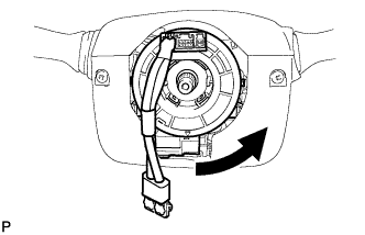
Rotate the spiral cable counterclockwise slowly by hand until it stops.
Note
Do not turn the spiral cable using the airbag wire harness.
-
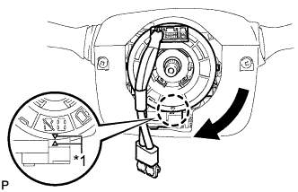
Text in Illustration *1 Alignment Mark Rotate the spiral cable clockwise approximately 2.5 turns to align the marks.
Note
Do not turn the spiral cable using the airbag wire harness.
Tech Tips
The spiral cable will rotate approximately 2.5 turns to both the left and right from the center.
-
-
INSTALL STEERING WHEEL ASSEMBLY
-
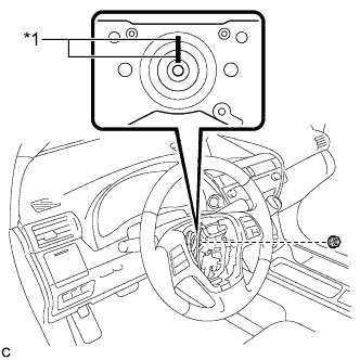
Text in Illustration *1 Matchmark Align the matchmarks on the steering wheel assembly and steering main shaft.
-
Install the steering wheel assembly set nut.
- Torque:
- 50 N*m { 510 kgf*cm, 37 ft.*lbf }
-
Connect the connectors to the spiral cable sub-assembly.
-
-
INSPECT STEERING WHEEL CENTER POINT
-
INSTALL STEERING PAD
-
Check that the power switch is off.
-
Check that the cable is disconnected from the negative (-) battery terminal.
CAUTION:
Wait at least 90 seconds after disconnecting the cable from the negative (-) battery terminal to disable the SRS system.
-
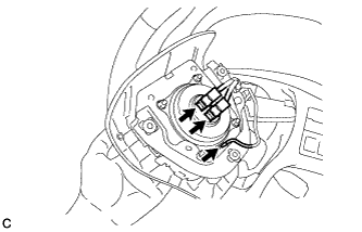
Connect the airbag connectors to the steering pad.
Note
-
When connecting any airbag connector, take care not to damage the airbag wire harness.
-
Be sure to only connect the connectors to each corresponding color.
-
-
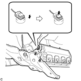
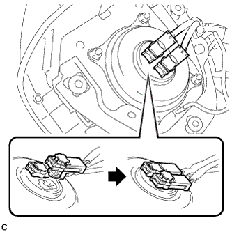
Push in the lock to install the airbag connector.
-
Connect the horn connector to the steering pad.
-
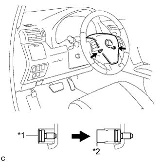
Text in Illustration *1 "TORX" Screw *2 Screw Case Confirm that the circumference groove of each "TORX" screw fits in the screw case, and place the steering pad onto the steering wheel assembly.
-
Using a T30 "TORX" socket wrench, tighten the 2 "TORX" screws.
- Torque:
- 8.8 N*m { 90 kgf*cm, 78 in.*lbf }
-
-
INSTALL LOWER NO. 3 STEERING WHEEL COVER
-
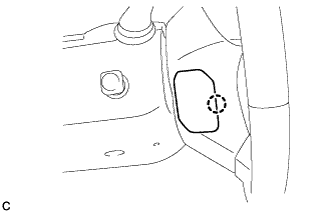
Engage the claw to install the lower No. 3 steering wheel cover.
-
-
INSTALL LOWER NO. 2 STEERING WHEEL COVER
-
Engage the claw to install the lower No. 2 steering wheel cover.
-
-
CONNECT CABLE TO NEGATIVE BATTERY TERMINAL
Note
-
Make sure that the cable has been disconnected from the negative (-) battery terminal for at least 2 seconds before reconnecting the cable.
-
Reset the auto tilt away function setting to the previous condition by changing the customize parameter Click here.
-
When disconnecting the cable, some systems need to be initialized after the cable is reconnected Click here.
-
-
INSTALL REAR DECK FLOOR BOX
-

Install the rear deck floor box with the 3 clips.
-
-
INSPECT SHIFT LEVER POSITION
-
When moving the shift lever from P to R with the power switch on (IG) and the brake pedal depressed, make sure that the shift lever moves smoothly and correctly into position.
-
Turn the power switch on (READY) and make sure that the vehicle moves forward when moving the shift lever from N to D and moves rearward when moving the shift lever to R.
If the operation cannot be performed as specified, inspect the shift lever position sensor and check the shift lever assembly installation condition.
-
-
ADJUST SHIFT LEVER POSITION
-
Apply the parking brake and move the shift lever to N.
Note
Check that the control shaft lever and the shift lever are in neutral.
-
Remove the No. 1 engine under cover.
-
Remove the nut from the control shaft lever.
-
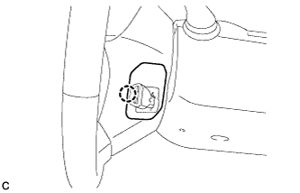
Using a screwdriver, disengage the 4 claws and disconnect the control cable with clip from the control cable bracket.
-
Remove the clip.
-
Turn back the boot.
-
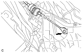
Text in Illustration *1 Slider *2 Lock Piece Slide the slider of the transmission control cable in the direction indicated by the arrow and pull the lock piece outward.
-
Install a new clip to the control cable bracket.
-
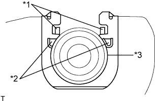
Text in Illustration *1 Claw A *2 Claw B *3 Control Cable Install the control cable to the control cable bracket.
Note
-
Make sure that the claws A on the clip are securely fit into the bracket holes.
-
Make sure that the cable is securely installed inside of the claws B of the clip.
-
-
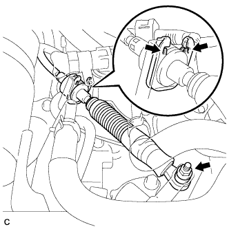
Text in Illustration *1 Lock Piece Connect the transmission control cable to the control shaft lever with the nut.
- Torque:
- 12 N*m { 122 kgf*cm, 9 ft.*lbf }
Note
Check that the lock piece is pulled up.
-
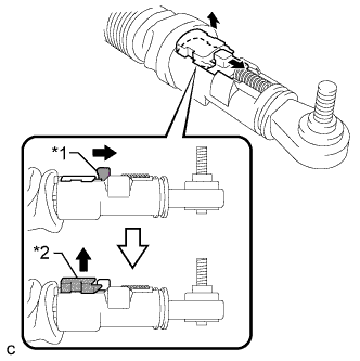
Text in Illustration *1 Lock Piece Push the lock piece into the adjuster case.
Note
-
Check that the shift lever position sensor and the shift lever are in neutral.
-
Securely push in the lock piece until the slider lock is engaged.
-
-
Refit the boot.
-
After adjusting the shift lever position, check the operation and function of the shift lever. If there is a problem, adjust the position again.
-
Install the No. 1 engine under cover.
-
-
INSPECT SHIFT LEVER OPERATION
-
While moving the shift lever from N to each position, check that the lever moves smoothly and that the shift position indicator comes on properly according to the shift lever position.
-
Turn the power switch on (READY) and check the following:
-
When the shift lever is moved to D, the vehicle moves forward.
-
When the shift lever is moved to R, the vehicle moves in reverse.
Note
The vehicle should not move when the shift position indicator is off.
-
-
-
INSPECT SUSPENSION CONTROL SYSTEM (w/ Air Suspension)
-
INSPECT SRS WARNING LIGHT