AIR CONDITIONING SYSTEM, Diagnostic DTC:B1498/98

| DTC Code | DTC Name |
|---|---|
| B1498/98 | Communication Malfunction (A/C Inverter Local) |
DESCRIPTION
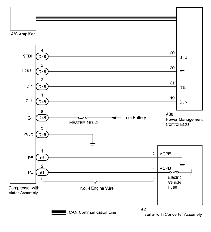
The power management control ECU and compressor with motor assembly transmit information to one another via a communication line. Compressor control is stopped and the DTC is output if communication information is cut off or abnormal information occurs.
The DTC is also detected if high-voltage power supplied from the inverter with converter assembly to the compressor control circuit is shut off.
The output DTC is memorized as previous trouble.
| DTC No. | DTC Detection Condition | Trouble Area |
|---|---|---|
| B1498/98 |
|
|
WIRING DIAGRAM
INSPECTION PROCEDURE
CAUTION:
-
Wear electrically insulated gloves and pull out the service plug grip before inspection as procedures may require disconnecting high-voltage connectors. Be sure to carry the removed service plug grip because other workers may install it by mistake.
-
Do not touch the high-voltage connectors or terminals for 10 minutes after the service plug grip is removed.
Note
-
The hybrid control system and air conditioning system output DTCs separately. Inspect DTCs following the flow chart for the hybrid control system first if any DTCs from those systems are output simultaneously.
-
Depending on the timing of the power supply to the 12 V power supply circuit and high-voltage circuit when the power switch is turned on (READY), an abnormal information signal may be output, causing this DTC to be stored. If the output DTC is a code that was memorized in the past, check the fuses and wire harnesses. If there is no malfunction, erase the DTC.
-
Inspect the fuses for circuits related to this system before performing the following inspection procedure.
PROCEDURE
-
CHECK CAN COMMUNICATION SYSTEM
-
Using the intelligent tester to check if the CAN communication system is functioning normally.
Result Result Proceed to CAN DTC is not output A CAN DTC is output B
B 
GO TO CAN COMMUNICATION SYSTEM Click here
A 
-
-
CHECK DIAGNOSTIC TROUBLE CODE
-
Check if DTCs for the hybrid control system are output using the intelligent tester.
Result Result Proceed to DTC is not output A Only DTC P3108 is output A DTCs other than P3108 are output B
B
GO TO HYBRID CONTROL SYSTEM Click here
A
-
-
CHECK HARNESS AND CONNECTOR (COMPRESSOR WITH MOTOR ASSEMBLY - BODY GROUND)
CAUTION:
Do not disconnect the connector on the high-voltage side.
-
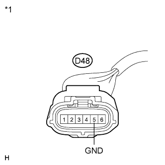
Text in Illustration *1 Front view of wire harness connector
(to Compressor with Motor Assembly)
Disconnect the compressor with motor assembly connector.
-
Measure the resistance according to the value(s) in the table below.
Standard Resistance Tester Connection Condition Specified Condition D48-5 (GND) - Body ground Always Below 1 Ω
NG
REPAIR OR REPLACE HARNESS OR CONNECTOR
OK
-
-
CHECK HARNESS AND CONNECTOR (COMPRESSOR WITH MOTOR ASSEMBLY - BATTERY, GROUND)
-
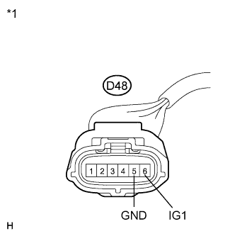
Text in Illustration *1 Front view of wire harness connector
(to Compressor with Motor Assembly)
Measure the voltage according to the value(s) in the table below.
Standard Voltage Tester Connection Condition Specified Condition D48-6 (IG1) - D48-5 (GND) Power switch on (IG) 11 to 14 V D48-6 (IG1) - D48-5 (GND) Power switch off Below 1 V
NG
REPAIR OR REPLACE HARNESS OR CONNECTOR
OK
-
-
CHECK HARNESS AND CONNECTOR (POWER MANAGEMENT CONTROL ECU - COMPRESSOR WITH MOTOR)
-
Disconnect the power management control ECU connector.
-
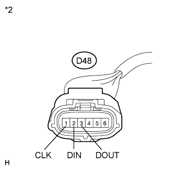
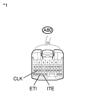
Text in Illustration *1 Front view of wire harness connector
(to Power Management Control ECU)
*2 Front view of wire harness connector
(to Compressor with Motor Assembly)
Measure the resistance according to the value(s) in the table below.
Standard Resistance Tester Connection Condition Specified Condition D48-1 (CLK) - A80-19 (CLK) Always Below 1 Ω D48-2 (DIN) - A80-31 (ITE) Always Below 1 Ω D48-3 (DOUT) - A80-30 (ETI) Always Below 1 Ω D48-1 (CLK) - Body ground Always 10 kΩ or higher D48-2 (DIN) - Body ground Always 10 kΩ or higher D48-3 (DOUT) - Body ground Always 10 kΩ or higher
NG
REPAIR OR REPLACE HARNESS OR CONNECTOR
OK
-
-
INSPECT ELECTRIC VEHICLE FUSE
CAUTION:
Be sure to wear insulated gloves.
-
Turn the power switch off.
-
Remove the service plug grip.
CAUTION:
Do not touch the high-voltage connectors or terminals for 10 minutes after the service plug grip is removed.
Note
Do not start the engine with the service plug grip removed because it may cause a malfunction.
-
Remove the inverter terminal cover.
Note
Be sure to prevent foreign objects or water from entering the inverter with converter assembly.
-
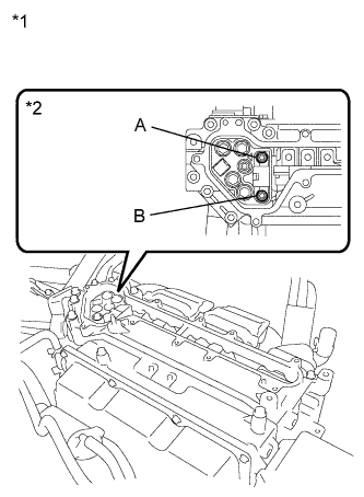
Text in Illustration *1 Inverter with Converter Assembly *2 Electric Vehicle Fuse Check that bolts A and B are tightened securely.
-
Measure the resistance according to the value(s) in the table below.
Standard Resistance Tester Item
(Tester Connection)
Condition Specified Condition ELECTRIC VEHICLE fuse
(A - B)
Always Below 1 Ω
NG
REPLACE ELECTRIC VEHICLE FUSE Click here
OK
-
-
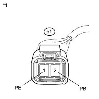
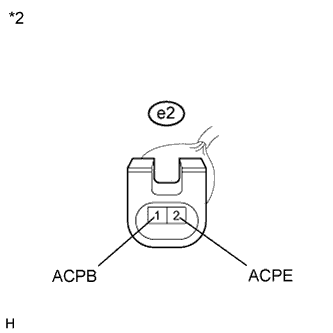
INSPECT NO. 4 ENGINE WIRE
CAUTION:
Be sure to wear insulated gloves.
-
Disconnect the No. 4 engine wire connector.
-
Text in Illustration *1 Front view of wire harness connector
(to Compressor with Motor Assembly)
*2 Front view of wire harness connector
(to Inverter with Converter Assembly)
Measure the resistance according to the value(s) in the table below.
Standard Resistance Tester Connection Condition Specified Condition e1-1 (PE) - e2-2 (ACPE) Always Below 1 Ω e1-2 (PB) - e2-1 (ACPB) Always Below 1 Ω e1-1 (PE) - Body ground Always 10 kΩ or higher e1-2 (PB) - Body ground Always 10 kΩ or higher
NG
REPLACE NO. 4 ENGINE WIRE Click here
OK
-
-
REPLACE COMPRESSOR WITH MOTOR ASSEMBLY
-
Replace the compressor with motor assembly Click here.
Tech Tips
Since the compressor with motor assembly cannot be inspected while it is removed from the vehicle, replace the compressor with motor assembly with a new or a known good one and check that the condition returns to normal.
-
Check for the DTC Click here.
Result Result Proceed to DTC B1498/98 is not output A DTC B1498/98 is output
(for LHD)
B DTC B1498/98 is output
(for RHD)
C
B
REPLACE POWER MANAGEMENT CONTROL ECU (for LHD) Click here
C
REPLACE POWER MANAGEMENT CONTROL ECU (for RHD) Click here
A 
END (COMPRESSOR WITH MOTOR ASSEMBLY WAS DEFECTIVE)
-