REAR SUSPENSION MEMBER INSTALLATION

-
INSTALL HOLE PLUG
-
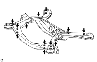
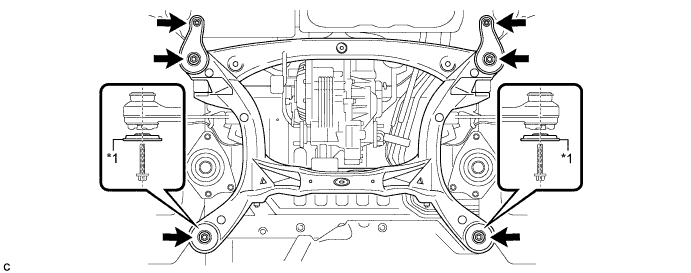
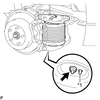
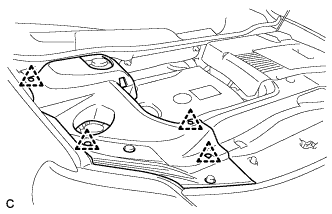
Install the 12 hole plugs to the rear suspension member sub-assembly as shown in the illustration.
Tech Tips
The upper and lower suspension member hole plug shapes are different.
-
-
INSTALL BOLT (for 2WD)
-
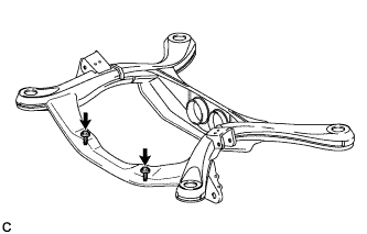
Install the 2 bolts to the rear suspension member sub-assembly as shown in the illustration.
-
-
INSTALL REAR SUSPENSION MEMBER FRONT BODY MOUNTING CUSHION (for LH Side)
-
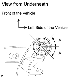
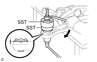
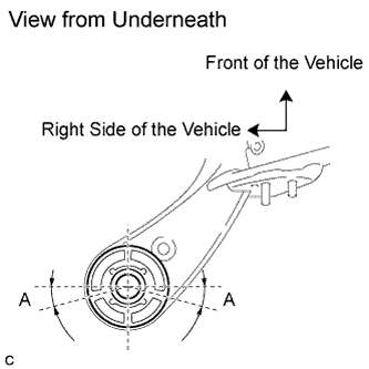
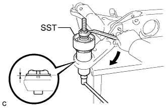
Temporarily install the rear suspension member front body mounting cushion (LH side) while confirming the installation direction.
Standard (A) 45° +/- 5° -
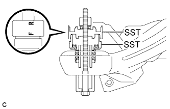
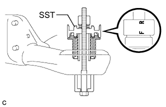
Install SST as shown in the illustration.
- SST
- 09527-17011
- 09830-10010 ( 09830-01010, 09830-01020, 09830-01030, 09830-01060 )
Note
Before using SST, apply grease to the SST bolts.
Tech Tips
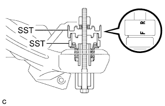
Use SST with the "F" mark facing the rear suspension member front body mounting cushion.
-
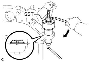
Using SST, install the rear suspension member front body mounting cushion (LH side) until there is no clearance between the rear suspension member sub-assembly and the rear suspension member front body mounting cushion (LH side).
- SST
- 09527-17011
- 09830-10010 ( 09830-01010, 09830-01020, 09830-01030, 09830-01060 )
Note
If the rear suspension member sub-assembly is scratched, apply paint to the scratched areas of the rear suspension member sub-assembly.
-
Remove SST from the rear suspension member sub-assembly.
-
-
INSTALL REAR SUSPENSION MEMBER FRONT BODY MOUNTING CUSHION (for RH Side)
-

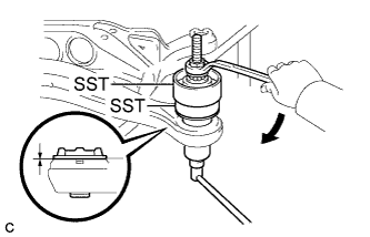
Temporarily install the rear suspension member front body mounting cushion (RH side) while confirming the installation direction.
Standard (A) 45° +/- 5° -
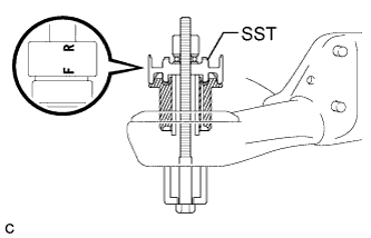
Install SST as shown in the illustration.
- SST
- 09527-17011
- 09830-10010 ( 09830-01010, 09830-01020, 09830-01030, 09830-01060 )
Note
Before using SST, apply grease to the SST bolts.
Tech Tips
Use SST with the "F" mark facing the rear suspension member front body mounting cushion.
-
Using SST, install the rear suspension member front body mounting cushion (RH side) until there is no clearance between the rear suspension member sub-assembly and the rear suspension member front body mounting cushion (RH side).
- SST
- 09527-17011
- 09830-10010 ( 09830-01010, 09830-01020, 09830-01030, 09830-01060 )
Note
If the rear suspension member sub-assembly is scratched, apply paint to the scratched areas of the rear suspension member sub-assembly.
-
Remove SST from the rear suspension member sub-assembly.
-
-
INSTALL REAR SUSPENSION MEMBER REAR BODY MOUNT CUSHION LH
-
Temporarily install the rear suspension member rear body mounting cushion LH while confirming the installation direction.
-
Install SST as shown in the illustration.
- SST
- 09830-10010 ( 09830-01010, 09830-01020, 09830-01030, 09830-01060 )
Note
Before using SST, apply grease to the SST bolts.
Tech Tips
Use SST with the "F" mark facing the rear suspension member rear body mounting cushion.
-
Using SST, install the rear suspension member rear body mounting cushion LH until there is no clearance between the rear suspension member sub-assembly and the rear suspension member rear body mounting cushion LH.
- SST
- 09830-10010 ( 09830-01010, 09830-01020, 09830-01030, 09830-01060 )
Note
If the rear suspension member sub-assembly is scratched, apply paint to the scratched areas of the rear suspension member sub-assembly.
-
Remove SST from the rear suspension member sub-assembly.
-
-
INSTALL REAR SUSPENSION MEMBER REAR BODY MOUNT CUSHION RH
-
Temporarily install the rear suspension member rear body mounting cushion RH while confirming the installation direction.
Standard (A) 15° +/- 5° -
Install SST as shown in the illustration.
- SST
- 09830-10010 ( 09830-01010, 09830-01020, 09830-01030, 09830-01060 )
Note
Before using SST, apply grease to the SST bolts.
Tech Tips
Use SST with the "F" mark facing the rear suspension member rear body mounting cushion.
-
Using SST, install the rear suspension member rear body mounting cushion RH until there is no clearance between the rear suspension member sub-assembly and the rear suspension member rear body mounting cushion RH.
- SST
- 09830-10010 ( 09830-01010, 09830-01020, 09830-01030, 09830-01060 )
Note
If the rear suspension member sub-assembly is scratched, apply paint to the scratched areas of the rear suspension member sub-assembly.
-
Remove SST from the rear suspension member sub-assembly.
-
-
INSTALL DIFFERENTIAL MOUNT CUSHION (for AWD)
-
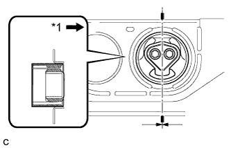
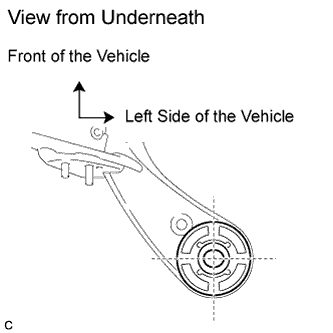
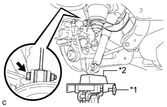
Text in Illustration *1 Front of the Vehicle As shown in the illustration, temporarily install the differential mount cushion to the rear suspension member sub-assembly from the rear of the vehicle.
Note
-
Make sure that the differential mount cushion is aligned within 3° from the center.
-
Be sure to install the differential mount cushion in the correct direction.
-
-
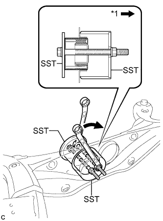
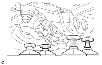
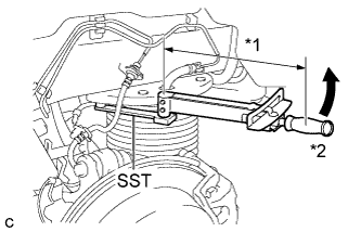
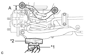
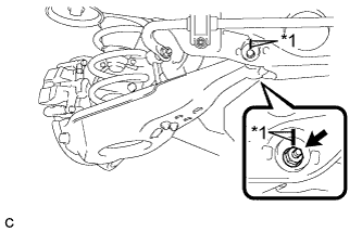
Text in Illustration *1 Front of the Vehicle Using SST, press the differential mount cushion into the rear suspension member sub-assembly. (Step *1)
- SST
- 09570-48010
Note
-
Before using SST, apply grease to the SST bolts.
-
Install the SST bolts straight and tighten them equally.
-
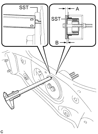
Using a vernier caliper, measure the length indicated by A in the illustration. (Step *2)
Note
-
Measure at several points to ensure that the differential mount cushion is pressed in evenly.
-
Do not measure on a weld bead.
-
-
Repeat the steps *1 and *2 to press the differential mount cushion into the rear suspension member sub-assembly until the length indicated by A in the illustration is within the specification.
Reference length (A) 6.5 to 7.5 mm (0.256 to 0.295 in.) Tech Tips
Reference length (A) = Standard length (B) + Thickness of SST
-
Remove SST. Using a vernier caliper, measure the differential mount cushion protrusion length indicated by B in the illustration and ensure that the measured length is within the specification.
Standard length (B) 0.5 to 1.5 mm (0.0197 to 0.0590 in.)
-
-
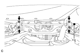
INSTALL REAR TRACTION WITH TRANSAXLE MOTOR ASSEMBLY (for AWD)
-
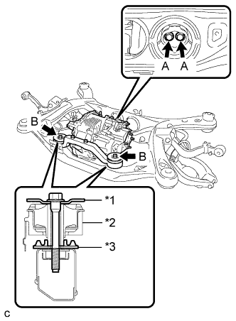
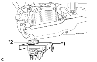
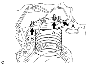
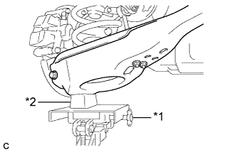
Text in Illustration *1 Upper Differential Mount Stopper *2 Front Differential Support Assembly *3 Lower Differential Mount Stopper Place the lower stopper, differential support assembly, rear traction with transaxle motor assembly, and upper stopper in this order. Install them to the rear suspension member with the 4 bolts.
- Torque:
- 95 N*m { 969 kgf*cm, 70 ft.*lbf, (for Bolt A) }
- Torque:
- 103 N*m { 1050 kgf*cm, 76 ft.*lbf, (for Bolt B) }
-
-
INSTALL REAR UPPER CONTROL ARM ASSEMBLY LH
-
Temporarily install the rear upper control arm assembly LH to the rear suspension member sub-assembly with the bolt and nut.
Note
-
Insert the bolt with the threaded end facing the rear of the vehicle.
-
Since the stopper nut is used, tighten the bolt.
-
-
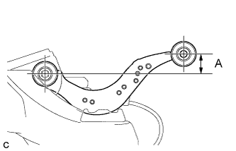
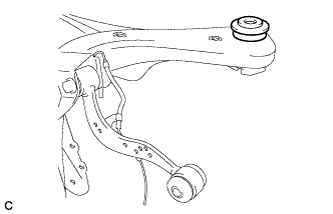
Set the rear upper control arm assembly LH in the tightening position as shown in the illustration.
Standard length (A) 24.3 mm (0.957 in.) -
Fully tighten the bolt in the tightening position.
- Torque:
- 120 N*m { 1224 kgf*cm, 89 ft.*lbf }
Note
Since the stopper nut is used, tighten the bolt.
-
-
INSTALL REAR UPPER CONTROL ARM ASSEMBLY RH
Tech Tips
Perform the same procedure as the LH side.
-
INSTALL REAR SPEED SENSOR WIRE LH (for 2WD)
-
Install the rear speed sensor wire LH with the 2 bolts and nut as shown in the illustration.
- Torque:
- Bolt
- 8.0 N*m { 82 kgf*cm, 71 in.*lbf }
- Nut
- 9.0 N*m { 92 kgf*cm, 80 in.*lbf }
Note
Do not twist the rear speed sensor wire LH when connecting it.
-
-
INSTALL REAR SPEED SENSOR LH (for AWD)
Tech Tips
Perform the same procedure as the rear speed sensor wire LH.
-
INSTALL REAR SPEED SENSOR WIRE RH (for 2WD)
-
Install the rear speed sensor wire RH with the 2 bolts and nut as shown in the illustration.
- Torque:
- Bolt
- 8.0 N*m { 82 kgf*cm, 71 in.*lbf }
- Nut
- 9.0 N*m { 92 kgf*cm, 80 in.*lbf }
Note
Do not twist the rear speed sensor wire RH when connecting it.
-
-
INSTALL REAR SPEED SENSOR RH (for AWD)
Tech Tips
Perform the same procedure as the rear speed sensor wire RH.
-
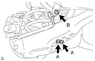
INSTALL REAR HEIGHT CONTROL SENSOR SUB-ASSEMBLY RH
-
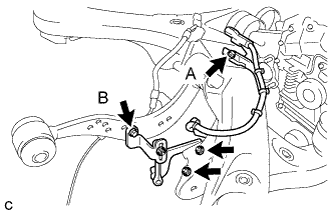
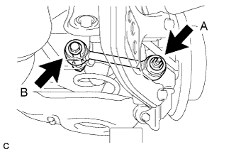
Install the rear height control sensor sub-assembly RH to the rear suspension member sub-assembly with the bolt (A) and 2 nuts.
- Torque:
- 5.0 N*m { 51 kgf*cm, 44 in.*lbf }
Note
Do not twist the rear height control sensor wire when connecting it.
-
Install the rear height control sensor sub-assembly RH to the rear upper control arm assembly RH with the bolt (B).
- Torque:
- 5.4 N*m { 55 kgf*cm, 48 in.*lbf }
-
-
INSTALL REAR HEIGHT CONTROL SENSOR SUB-ASSEMBLY LH (w/ Air Suspension)
-
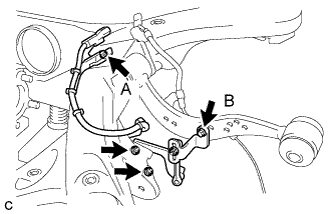
Install the rear height control sensor sub-assembly LH to the rear suspension member sub-assembly with the bolt (A) and 2 nuts.
- Torque:
- 5.0 N*m { 51 kgf*cm, 44 in.*lbf }
Note
Do not twist the rear height control sensor wire when connecting it.
-
Install the rear height control sensor sub-assembly LH to the rear upper control arm assembly LH with the bolt (B).
- Torque:
- 5.4 N*m { 55 kgf*cm, 48 in.*lbf }
-
-
INSTALL REAR SUSPENSION MEMBER UPPER STOPPER
-
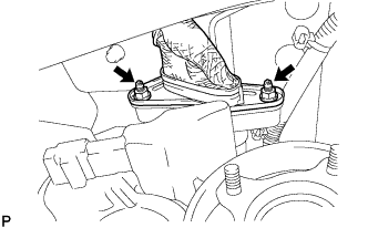
Install the 2 rear suspension member upper stoppers as shown in the illustration.
Note
Be sure to install the rear suspension member upper stoppers in the correct direction shown in the illustration.
-
-
INSTALL REAR SUSPENSION MEMBER REAR UPPER STOPPER
-
Install the 2 rear suspension member rear upper stoppers as shown in the illustration.
-
-
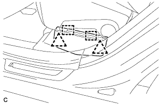
INSTALL REAR SUSPENSION MEMBER SUB-ASSEMBLY
Tech Tips
-
Use the same procedure for the 2WD and AWD.
-
The procedure listed below is for the AWD.
-
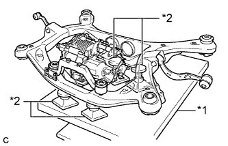
Text in Illustration *1 Jack *2 Attachment Support the rear suspension member with a jack using 4 attachments or equivalent tools as shown in the illustration.
Note
Make sure to secure the rear suspension member to prevent it from dropping.
Tech Tips
Keep the suspension member level.
-
Raise the rear suspension member until there is no clearance between the rear suspension member and the body.
Note
-
When raising the rear suspension member, be careful not to damage the vehicle body or other components installed on the vehicle.
-
Keep supporting the rear suspension member until the installation has been completed.
-
-
Temporarily tighten the rear No. 1 suspension arm assembly LH.
-
Text in Illustration *1 Jack *2 Wooden Block Using a jack and wooden block, jack up the rear axle assembly LH to replicate standard vehicle height conditions.
-
Temporarily tighten the rear No. 1 suspension arm assembly LH to the rear axle carrier sub-assembly LH with the spacer and nut (A).
Note
Fully tighten the nut (A) after stabilizing the suspension.
-
Temporarily tighten the rear No. 1 suspension arm assembly LH to the rear suspension member with the bolt (B) and nut.
Note
-
Insert the bolt with the threaded end facing the rear of the vehicle.
-
Since the stopper nut is used, tighten the bolt (B).
-
Fully tighten the bolt (B) after stabilizing the suspension.
-
-
Slowly lower the rear axle assembly LH.
-
-
Temporarily tighten the rear No. 1 suspension arm assembly RH.
Tech Tips
Perform the same procedure as the LH side.
-
Install the rear suspension member with the 2 rear lower suspension braces, 2 rear lower suspension member stoppers, 4 bolts and 2 nuts.
Text in Illustration *1 Rear Lower Suspension Brace - Torque:
- Bolt
- 158 N*m { 1612 kgf*cm, 117 ft.*lbf }
- Nut
- 32 N*m { 327 kgf*cm, 24 ft.*lbf }
Note
Be sure to install the rear suspension member with the rear lower suspension braces facing in the correct direction as shown in the illustration.
-
Lower the jack.
-
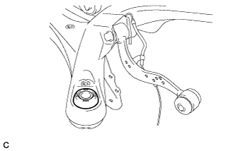
Connect the rear upper control arm assembly LH.
-
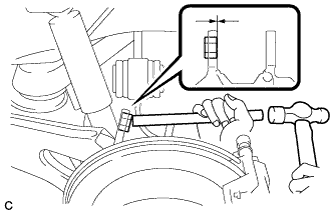
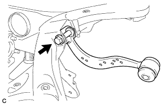
Using a brass bar and a hammer, push out the bushing until it is positioned as shown in the illustration.
Tech Tips
Pushing out the bushing makes it easier to connect the rear upper control arm assembly LH.
-
Text in Illustration *1 Jack *2 Wooden Block Using a jack and wooden block, jack up the rear axle assembly LH to replicate standard vehicle height conditions.
-
Connect the rear upper control arm assembly LH to the rear axle carrier sub-assembly LH with the bolt and nut.
- Torque:
- 145 N*m { 1479 kgf*cm, 107 ft.*lbf }
Note
-
Insert the bolt with the threaded end facing the rear of the vehicle.
-
Since the stopper nut is used, tighten the bolt.
-
Slowly lower the rear axle assembly LH.
-
-
Connect the rear upper control arm assembly RH.
Tech Tips
Perform the same procedure as the LH side.
-
-
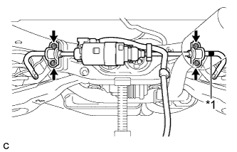
INSTALL NO. 3 WIRE FRAME (for AWD)
Note
Wear insulated gloves.
-
Wear insulated gloves. Install the No. 3 wire frame to the rear traction with transaxle motor with the 2 nuts.
- Torque:
- 15 N*m { 153 kgf*cm, 11 ft.*lbf }
-
Install the wire harness clamp to the vehicle with the nut.
- Torque:
- 8.5 N*m { 87 kgf*cm, 75 in.*lbf }
-
Install the ground cable to the rear traction with transaxle motor with the nut.
- Torque:
- 5.5 N*m { 56 kgf*cm, 49 in.*lbf }
-
Connect the 2 connectors and clamp to the rear traction with transaxle motor.
-
-
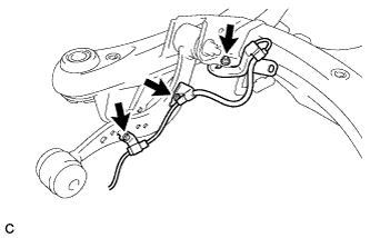
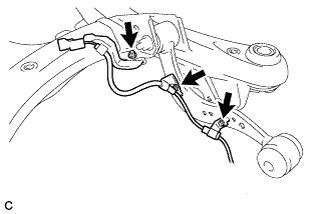
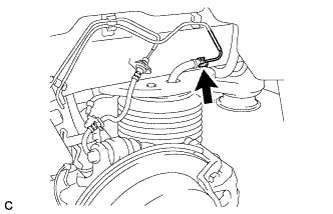
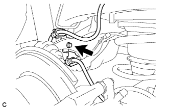
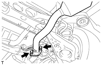
INSTALL FRAME WIRE
-
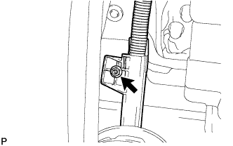
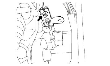
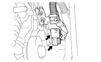
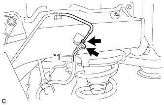
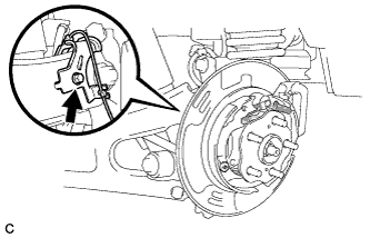
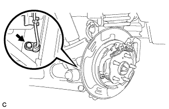
Install the bolt and engage the clamps, and then connect the connectors to install the frame wire to the rear suspension member as shown in the illustration.
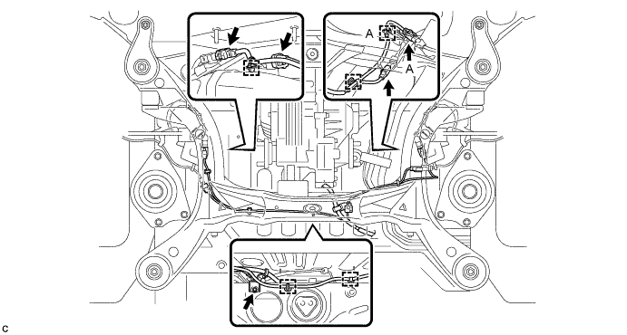
- Torque:
- 5.0 N*m { 51 kgf*cm, 44 in.*lbf }
Note
Do not twist the frame wire when installing it.
Tech Tips
-
There are only the connector (A) and the clamp (A) on vehicles with the air suspension.
-
Use the same procedure for the 2WD and AWD.
-
-
TEMPORARILY TIGHTEN REAR NO. 2 SUSPENSION ARM ASSEMBLY LH
w/o Air Suspension: Click here
w/ Air Suspension: Click here
-
TEMPORARILY TIGHTEN REAR NO. 2 SUSPENSION ARM ASSEMBLY RH
Tech Tips
Perform the same procedure as the LH side.
-
INSTALL REAR PNEUMATIC CYLINDER ASSEMBLY LH (w/ Air Suspension)
-
Install 2 new O-rings, a new plate, a new No. 2 connector to the rear pneumatic cylinder assembly.
Note
Perform this procedure when reusing the rear pneumatic cylinder assembly.
Tech Tips
For the installing procedure of the tube (type 2), refer to Precaution of the suspension control system Click here.
-
Text in Illustration *1 Positioning Pin Install the rear pneumatic cylinder assembly to the rear No. 2 suspension arm assembly with the nut.
- Torque:
- 80 N*m { 816 kgf*cm, 59 ft.*lbf }
Note
When installing the rear pneumatic cylinder assembly, first insert the positioning pin into the hole.
-
Text in Illustration *1 Jack *2 Wooden Block Jack up the rear axle assembly to install the rear pneumatic cylinder assembly, placing a wooden block underneath to avoid damage.
-
Temporarily install the rear pneumatic cylinder assembly to the body with the 3 bolts, and then fully tighten the 2 bolts (A).
- Torque:
- 50 N*m { 510 kgf*cm, 37 ft.*lbf }
-
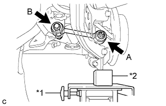
Text in Illustration *1 Fulcrum Length *2 Turn Using SST and a socket wrench, fully tighten the bolt (B).
- SST
- 09961-00950
- Torque:
- without SST
- 50 N*m { 510 kgf*cm, 37 ft.*lbf }
- with SST
- 35 N*m { 355 kgf*cm, 26 ft.*lbf }
Note
-
Use a torque wrench with a fulcrum length of 345 mm (1.13 ft.).
-
This torque value is effective when SST is parallel to the torque wrench.
-
Slowly lower the rear axle assembly.
-
Connect the air tube to the rear pneumatic cylinder assembly.
Tech Tips
For the connecting procedure of the tube (type 2), refer to Precaution of the suspension control system Click here.
-
-
INSTALL REAR PNEUMATIC CYLINDER ASSEMBLY RH (w/ Air Suspension)
Tech Tips
Perform the same procedure as the LH side.
-
INSTALL REAR STABILIZER BAR (w/o Active Stabilizer System)
-
Text in Illustration *1 Identification Mark Install the rear stabilizer bar with 2 rear stabilizer bushings and 2 rear No. 1 stabilizer bar brackets with the 4 nuts.
- Torque:
- 75 N*m { 765 kgf*cm, 55 ft.*lbf }
Note
Ensure that the identification mark is on the right side of the vehicle.
-
-
INSTALL REAR ACTIVE STABILIZER CONTROL ACTUATOR ASSEMBLY (w/ Active Stabilizer System)
-
Text in Illustration *1 Identification Mark Install the rear active stabilizer control actuator assembly with 2 rear stabilizer bushings and 2 rear No. 1 stabilizer bar brackets with the 4 nuts.
- Torque:
- 75 N*m { 765 kgf*cm, 55 ft.*lbf }
Note
-
Ensure that the identification mark is on the right side of the vehicle.
-
Take care not to damage the wire harness and connectors of the rear active stabilizer control actuator assembly.
-
Avoid any impact to the rear active stabilizer control actuator assembly.
-
Do not drop the rear active stabilizer control actuator assembly. If it is dropped, replace it with a new one.
-
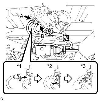
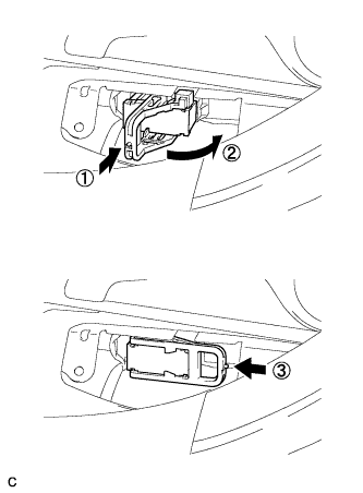
Using the procedures below, connect the connector (A).
-
Connect the connector (A).*1
-
Rotate the lever in the direction of the arrow until a "click" sound is heard.*2
-
Lock the lever's lock.*3
-
-
Engage the 2 clamps and connect the connector (B).
-
-
INSTALL NO. 2 LUGGAGE COMPARTMENT SIDE COVER PROTECTOR (w/ Active Stabilizer System)
-
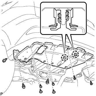
Engage the 2 craws and install the No. 2 luggage compartment side cover protector.
-
Install the 3 clips and 2 bolts.
-
Install the 4 screws.
- Torque:
- 7.5 N*m { 77 kgf*cm, 66 in.*lbf }
-
Install the 2 screws.
- Torque:
- 7.5 N*m { 77 kgf*cm, 66 in.*lbf }
-
Install a new grommet.
-
-
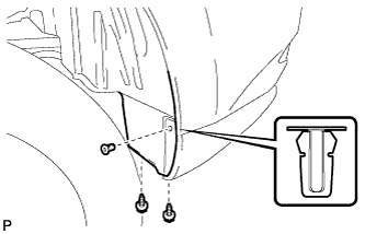
INSTALL REAR QUARTER PANEL MUDGUARD SUB-ASSEMBLY LH (w/ Active Stabilizer System)
-
Install the rear quarter panel mudguard sub-assembly Click here.
Tech Tips
This step is not necessary for vehicles without the rear fender mudguard.
-
-
INSTALL REAR STABILIZER LINK SUB-ASSEMBLY (for LH Side)
-
Install the rear stabilizer link sub-assembly to the rear stabilizer bar with the nut (B).
- Torque:
- 90 N*m { 918 kgf*cm, 66 ft.*lbf }
Tech Tips
If the ball joint turns together with the nut (B), use a hexagon wrench (6 mm) to hold the stud bolt.
-
Install the rear stabilizer link sub-assembly to the rear No. 2 suspension arm assembly with the 2 nuts (A).
- Torque:
- 82 N*m { 836 kgf*cm, 60 ft.*lbf }
-
-
INSTALL REAR STABILIZER LINK SUB-ASSEMBLY (for RH Side)
Tech Tips
Perform the same procedure as the LH side.
-
INSTALL REAR FLEXIBLE HOSE LH
-
Install the rear flexible hose LH to the rear upper control arm assembly LH with the bolt.
- Torque:
- 19 N*m { 192 kgf*cm, 14 ft.*lbf }
Note
-
Do not twist the rear flexible hose when connecting it.
-
Do not damage the rear flexible hose when reassembling it.
-
If the rear flexible hose is damaged, replace it with a new one.
-
Text in Illustration *1 Identification Mark Install the rear flexible hose LH to the bracket with a new clip.
Note
-
Install the clip as far as it will go.
-
Do not twist the rear flexible hose when installing it.
-
When installing the rear flexible hose, face the identification mark to the outside of the vehicle and minimize twisting of the hose.
-
-
Using a union nut wrench, connect the brake line to the rear flexible hose LH.
- Torque:
- 15 N*m { 155 kgf*cm, 11 ft.*lbf }
Note
-
Do not bend or damage the brake line.
-
Do not allow any foreign matter such as dirt and dust to enter the brake line.
-
Use the formula to calculate special torque values for situations where the union nut wrench is combined with a torque wrench Click here.
-
-
INSTALL REAR FLEXIBLE HOSE RH
Tech Tips
Perform the same procedure as the LH side.
-
INSTALL REAR DRIVE SHAFT ASSEMBLY LH (for AWD)
-
Text in Illustration *1 Jack *2 Wooden Block Using a jack and wooden block, jack up the rear No. 2 suspension arm assembly to replicate standard vehicle height conditions.
Note
Do not jack up the rear No. 2 suspension arm assembly too high as the vehicle may fall.
-
Text in Illustration *1 Matchmark Align the matchmarks on the rear drive shaft assembly and rear axle hub and bearing assembly, and then insert the rear drive shaft assembly to the rear axle hub and bearing assembly.
-
Align the matchmarks.
-
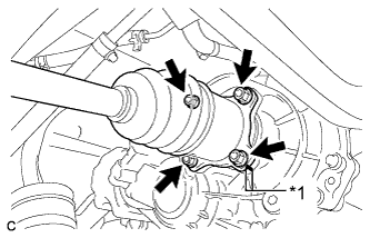
Text in Illustration *1 Matchmark Install the rear drive shaft assembly with the 4 nuts and washers.
- Torque:
- 56 N*m { 571 kgf*cm, 41 ft.*lbf }
-
-
INSTALL REAR DRIVE SHAFT ASSEMBLY RH (for AWD)
Tech Tips
Perform the same procedure as the LH side.
-
INSTALL REAR AXLE SHAFT NUT LH (for AWD)
-
Clean the threaded parts on the rear drive shaft assembly and a new rear axle shaft nut using a non-residue solvent.
Note
-
Be sure to perform this work for a new rear drive shaft assembly.
-
Keep the threaded parts free of oil and foreign matter.
-
-
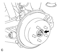
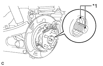
While applying the parking brakes, install the new rear axle shaft nut.
- Torque:
- 294 N*m { 2998 kgf*cm, 217 ft.*lbf }
-
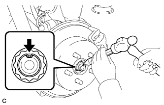
Using a chisel and a hammer, stake the rear axle shaft nut.
-
-
INSTALL REAR AXLE SHAFT NUT RH (for AWD)
Tech Tips
Perform the same procedure as the LH side.
-
INSTALL REAR SPEED SENSOR WIRE LH (for 2WD)
-
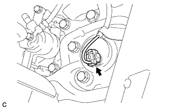
Connect the connector to the rear speed sensor.
-
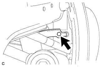
Install the No. 1 bracket with the bolt.
- Torque:
- 8.0 N*m { 82 kgf*cm, 71 in.*lbf }
-
-
INSTALL REAR SPEED SENSOR WIRE RH (for 2WD)
Tech Tips
Perform the same procedure as the LH side.
-
INSTALL REAR SPEED SENSOR LH (for AWD)
-
Install the rear speed sensor to the rear trailing arm assembly with the bolt.
- Torque:
- 8.0 N*m { 82 kgf*cm, 71 in.*lbf }
Note
Do not twist the rear speed sensor when installing it.
-
Install the rear speed sensor to the rear axle carrier sub-assembly with the bolt.
- Torque:
- 8.0 N*m { 82 kgf*cm, 71 in.*lbf }
Note
-
Prevent foreign matter from attaching to the rear speed sensor tip.
-
Do not file the rear speed sensor installation hole or surface because the gap between the magnet rotor and rear speed sensor is important.
-
Do not twist or apply excessive force to the rear speed sensor during installation to prevent it from being damaged.
-
Do not twist the rear speed sensor when installing it.
-
-
INSTALL REAR SPEED SENSOR RH (for AWD)
Tech Tips
Perform the same procedure as the LH side.
-
INSTALL CENTER EXHAUST PIPE ASSEMBLY (w/o Exhaust Heat Recirculation System)
-
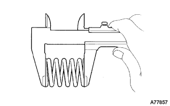
Using a vernier caliper, measure the free length of the compression springs.
Minimum length 41.5 mm (1.64 in.) If the free length is less than the minimum, replace the compression spring.
-
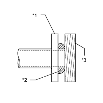
Fully insert a new gasket to the front No. 3 exhaust pipe sub-assembly.
-
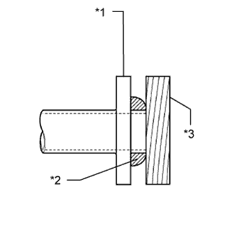
Text in Illustration *1 Front No. 3 Exhaust Pipe Sub-assembly *2 Gasket *3 Wooden Block Using a plastic hammer and wooden block, tap in the new gasket until its surface is flush with the front No. 3 exhaust pipe sub-assembly.
Note
-
Be sure to install the gasket in the correct direction.
-
Do not reuse the gasket.
-
Do not damage the gasket.
-
Do not push in the gasket by using the exhaust pipe when connecting it.
-
-
Connect the center exhaust pipe assembly to the 4 exhaust pipe supports.
-
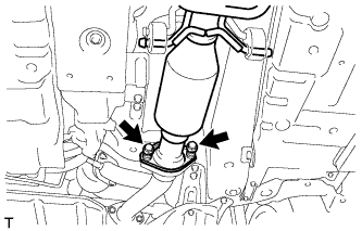
Install the center exhaust pipe assembly with the 2 bolts and 2 compression springs.
- Torque:
- 43 N*m { 440 kgf*cm, 32 ft.*lbf }
-
-
INSTALL CENTER EXHAUST PIPE ASSEMBLY (w/ Exhaust Heat Recirculation System)
Note
When removing or installing the center exhaust pipe assembly, do not subject the temperature switch to impacts.
-
Using a vernier caliper, measure the free length of the compression springs.
Minimum length 41.5 mm (1.64 in.) If the free length is less than the minimum, replace the compression spring.
-
Fully insert a new gasket to the front No. 3 exhaust pipe sub-assembly.
-
Text in Illustration *1 Front No. 3 Exhaust Pipe Sub-assembly *2 Gasket *3 Wooden Block Using a plastic hammer and wooden block, tap in the new gasket until its surface is flush with the front No. 3 exhaust pipe sub-assembly.
Note
-
Be sure to install the gasket in the correct direction.
-
Do not reuse the gasket.
-
Do not damage the gasket.
-
Do not push in the gasket by using the exhaust pipe when connecting it.
-
-
Connect the center exhaust pipe assembly to the 4 exhaust pipe supports.
-
Install the center exhaust pipe assembly with the 2 bolts and 2 compression springs.
- Torque:
- 43 N*m { 440 kgf*cm, 32 ft.*lbf }
-
Connect the 2 heater water hoses.
-
-
INSTALL HEATER COVER (w/ Exhaust Heat Recirculation System)
-
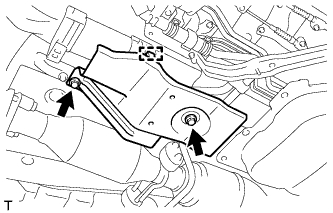
Install the heater cover with the 2 bolts.
- Torque:
- 9.8 N*m { 100 kgf*cm, 87 in.*lbf }
-
Connect the clamp.
-
-
INSTALL TAIL EXHAUST PIPE ASSEMBLY
-
Using a vernier caliper, measure the free length of the compression springs.
Minimum length 41.5 mm (1.64 in.) If the free length is less than the minimum, replace the compression spring.
-
Fully insert a new gasket to the center exhaust pipe assembly.
-
Text in Illustration *1 Center Exhaust Pipe Assembly *2 Gasket *3 Wooden Block Using a plastic hammer and wooden block, tap in the new gasket until its surface is flush with the center exhaust pipe assembly.
Note
-
Be sure to install the gasket in the correct direction.
-
Do not reuse the gasket.
-
Do not damage the gasket.
-
Do not push in the gasket by using the exhaust pipe when connecting it.
-
-
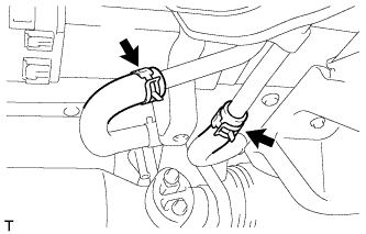
Connect the tail exhaust pipe assembly to the 2 exhaust pipe supports.
-
Install the tail exhaust pipe assembly with the 2 bolts and 2 compression springs.
- Torque:
- 43 N*m { 440 kgf*cm, 32 ft.*lbf }
-
-
CHECK HIGH VOLTAGE CABLE CONNECTION (for AWD)
Note
Be sure to wear insulated gloves and protective goggles.
-
Make sure that the No. 3 wire frame is securely installed with the nuts.
Note
-
Do not install the No. 3 wire frame at an angle.
-
Be sure to tighten the nuts securely.
-
-
-
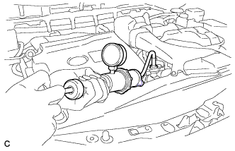
INSTALL SERVICE PLUG GRIP (for AWD)
CAUTION:
Wear insulated gloves.
Note
Before connecting the service plug, check that no parts and tools remain and that the high voltage terminals and connectors are connected securely.
-
Wear insulated gloves and insert the service plug grip in the order shown in the illustration.
-
Tilt the service plug grip 90° and slide it down until a click sound is heard.
-
-
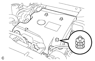
INSTALL BATTERY SERVICE HOLE COVER (for AWD)
-
Engage the 2 clips, 2 guides and install the battery service hole cover.
Note
Make sure that the battery service hole cover is installed securely.
-
-
CONNECT CABLE TO NEGATIVE BATTERY TERMINAL
Note
When disconnecting the cable, some systems need to be initialized after the cable is reconnected Click here.
-
INSTALL REAR DECK FLOOR BOX
-

Install the rear deck floor box with the 3 clips.
-
-
BLEED BRAKE LINE
Tech Tips
Refer to the instructions for Bleed Brake Line Click here.
-
ADD ENGINE COOLANT (for Engine with Exhaust Heat Recirculation System)
-
Tighten the radiator drain cock plug by hand.
-
Tighten the 2 cylinder block drain cock plugs.
- Torque:
- 13 N*m { 130 kgf*cm, 9 ft.*lbf }
-
Loosen the air drain cock plug on the water inlet housing.
-
Add TOYOTA Super Long Life Coolant (SLLC) to the radiator inlet opening until coolant overflows from the air drain cock hole. Then tighten the air drain cock plug to the water inlet housing.
- Torque:
- 13 N*m { 130 kgf*cm, 9 ft.*lbf }
-
Slowly fill the radiator with TOYOTA Super Long Life Coolant (SLLC).
Standard Capacity Item Capacity Engine coolant 11.7 liters (12.4 US qts, 10.2 lmp. qts) Tech Tips
-
TOYOTA vehicles are filled with TOYOTA SLLC at the factory. In order to avoid damage to the engine cooling system and other technical problems, only use TOYOTA SLLC or similar high quality ethylene glycol based non-silicate, non-amine, non-nitrite, non-borate coolant with long-life hybrid organic acid technology (coolant with long-life hybrid organic acid technology is a combination of low phosphates and organic acids).
-
Contact your TOYOTA dealer for further details.
Note
Never use water as a substitute for engine coolant.
-
-
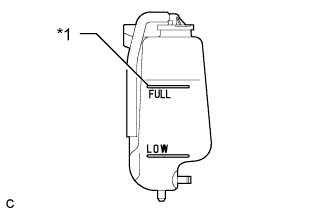
Text in Illustration *1 Full Line Slowly pour coolant into the radiator reservoir tank until it reaches the full line.
-
Install the radiator cap.
-
Squeeze the No. 1 and No. 2 radiator hoses several times by hand, and then check the level of the coolant.
If the coolant level is low, add coolant.
-
Bleed air from the cooling system.
-
Put the engine in inspection mode Click here.
-
Warm up the engine until the thermostat opens. While the thermostat is open, circulate the coolant for several minutes.
Tech Tips
The thermostat open timing can be confirmed by squeezing the No. 2 radiator hose by hand, and checking when the engine coolant starts to flow inside the hose.
-
Maintain the engine speed at 2500 rpm.
-
Squeeze the inlet and No. 1 and No. 2 radiator hoses several times by hand to bleed air.
CAUTION:
When squeezing the radiator hoses:
-
Wear protective gloves.
-
Be careful as the radiator hoses are hot.
-
Keep your hands away from the cooling fans.
Note
-
Make sure that the radiator reservoir still has some coolant in it.
-
If the coolant temperature gauge indicates an excessive temperature, turn off the engine and let it cool.
-
If there is not enough coolant, the engine may overheat or be seriously damaged.
-
If the radiator reservoir does not have enough coolant, perform the following: 1) stop the engine, 2) wait until the coolant has cooled down, and 3) add coolant until the reservoir is filled to the Full line.
-
-
-
Stop the engine and wait until the engine coolant cools down.
-
Add engine coolant to the full line on the radiator reservoir.
-
-
INSTALL FRONT FLOOR COVER LH (w/ Exhaust Heat Recirculation System)
-

Text in Illustration *1 Bolt *2 Screw Connect the 2 clips (B).
-
Install the front floor cover LH with the 2 screws and 4 bolts.
-
Install the clip (A).
-
-
INSPECT FOR COOLANT LEAK (for Engine with Exhaust Heat Recirculation System)
CAUTION:
Do not remove the radiator cap while the engine and radiator are still hot. Pressurized hot engine coolant and steam may be released and cause serious burns.
Note
Before performing each inspection, turn the A/C switch off.
-
Remove the radiator cap.
-
Fill the radiator with coolant and attach a radiator cap tester.
-
Put the engine in inspection mode Click here.
-
Warm up the engine.
-
Using the radiator cap tester, increase the pressure inside the radiator to 118 kPa (1.2 kgf/cm2, 17 psi), and check that the pressure does not drop.
If the pressure drops, check the hoses, radiator, exhaust center pipe assembly and the heater hose around the water temperature switch and engine water pump for leaks. If no external leaks are found, check the heater core, cylinder block and cylinder head.
-
Remove the radiator cap tester.
-
Install the radiator cap.
-
-
INSTALL NO.1 ENGINE UNDER COVER (w/ Exhaust Heat Recirculation System)
-
INSTALL V-BANK COVER SUB-ASSEMBLY (w/ Exhaust Heat Recirculation System)
-
Fit the 4 retainers and install the V-bank cover sub-assembly.
-
-
INSTALL COOL AIR INTAKE DUCT SEAL (w/ Exhaust Heat Recirculation System)
-
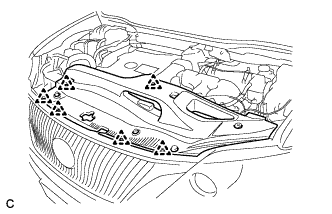
Install the cool air intake duct seal with the 6 clips.
-
-
INSTALL ENGINE ROOM SIDE COVER LH (w/ Exhaust Heat Recirculation System)
-
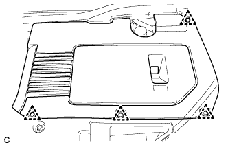
Install the engine room side cover with the 4 clips.
-
-
INSTALL ENGINE ROOM SIDE COVER (w/ Exhaust Heat Recirculation System)
-
Install the engine room side cover with the 4 clips.
-
-
INSPECT FOR EXHAUST GAS LEAK
-
STABILIZE SUSPENSION
-
Text in Illustration *1 Jack *2 Wooden Block Jack up the rear No. 2 suspension arm assembly, placing a wooden block underneath to avoid damage. Apply load to the suspension so that the rear upper control arm assembly is positioned as shown in the illustration.
Standard length (A) 24.3 mm (0.957 in.) CAUTION:
Do not jack up the rear No. 2 suspension arm assembly too high as the vehicle may fall.
Tech Tips
-
If the rear upper control arm assembly cannot be positioned as shown in the illustration even when the rear No. 2 suspension arm assembly is jacked up, apply additional load such as by placing a weight in the luggage compartment.
-
Use the same procedure for the RH side and LH side.
-
-
-
FULLY TIGHTEN REAR NO. 1 SUSPENSION ARM ASSEMBLY LH
-
Using a ball joint lock nut wrench, fully tighten the bolt (B).
- Torque:
- 150 N*m { 1530 kgf*cm, 111 ft.*lbf }
Note
-
The final torque must be applied under standard vehicle height conditions.
-
Since the stopper nut is used, tighten the bolt (B).
-
Use the formula to calculate special torque values for situations where the ball joint lock nut wrench is combined with a torque wrench Click here.
-
Fully tighten the nut (A).
- Torque:
- 150 N*m { 1530 kgf*cm, 111 ft.*lbf }
Note
The final torque must be applied under standard vehicle height conditions.
-
-
FULLY TIGHTEN REAR NO. 1 SUSPENSION ARM ASSEMBLY RH
Tech Tips
Perform the same procedure as the LH side.
-
FULLY TIGHTEN REAR NO. 2 SUSPENSION ARM ASSEMBLY LH
-
Text in Illustration *1 Matchmark Align the matchmarks on the adjust cams and rear suspension member sub-assembly.
-
Fully tighten the nut.
- Torque:
- 100 N*m { 1020 kgf*cm, 74 ft.*lbf }
Note
-
The final torque must be applied under standard vehicle height conditions.
-
When tightening the nut, keep the toe adjust cam from rotating.
-
-
FULLY TIGHTEN REAR NO. 2 SUSPENSION ARM ASSEMBLY RH
Tech Tips
Perform the same procedure as the LH side.
-
INSTALL REAR SUSPENSION ARM COVER LH
w/o Air Suspension: Click here
w/ Air Suspension: Click here
-
INSTALL REAR SUSPENSION ARM COVER RH
Tech Tips
Perform the same procedure as the LH side.
-
INSTALL REAR WHEELS
- Torque:
- 103 N*m { 1050 kgf*cm, 76 ft.*lbf }
-
INSPECT FOR AIR LEAK (w/ Air Suspension)
-
Inspect for air leaks Click here.
-
-
CHECK VEHICLE HEIGHT (w/ Air Suspension)
Note
If the height control sensor link is removed, check the vehicle height.
-
Change the height control switch from the "NORMAL" position to the "HIGH" position and back to the "NORMAL" position.
-
Measure the vehicle height Click here.
-
-
ADJUST VEHICLE HEIGHT (w/ Air Suspension)
Note
If the height control sensor has been replaced, be sure to adjust the vehicle height.
-
Adjust the vehicle height Click here.
-
-
INSPECT AND ADJUST REAR WHEEL ALIGNMENT
-
Inspect and adjust the rear wheel alignment Click here.
-
-
CHECK FOR SPEED SENSOR SIGNAL
-
Check for the speed sensor signal Click here.
-
-
HEIGHT CONTROL SENSOR SIGNAL INITIALIZATION (w/o Air Suspension)
-
Initialize the height control sensor signal Click here.
-
-
INSPECT AND ADJUST HEADLIGHT AIMING
for HID Headlight: Click here
for LED Headlight: Click here