REAR LOWER ARM INSTALLATION

Tech Tips
-
Use the same procedure for the RH side and LH side.
-
The procedure listed below is for the LH side.
-
TEMPORARILY TIGHTEN REAR NO. 1 SUSPENSION ARM ASSEMBLY
-
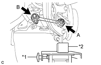
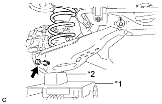
Text in Illustration *1 Jack *2 Wooden Block Using a jack and wooden block, jack up the rear axle assembly to replicate standard vehicle height conditions.
-
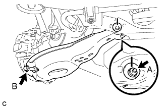
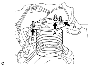
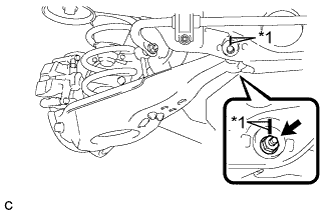
Temporarily tighten the rear No. 1 suspension arm assembly to the rear axle carrier sub-assembly with the spacer and nut (A).
Note
Fully tighten the nut (A) after stabilizing the suspension.
-
Temporarily tighten the rear No. 1 suspension arm assembly to the rear suspension member with the bolt (B) and nut.
Note
-
Insert the bolt with the threaded end facing the rear of the vehicle.
-
Since the stopper nut is used, tighten the bolt (B).
-
Fully tighten the bolt (B) after stabilizing the suspension.
-
-
Slowly lower the rear axle assembly.
-
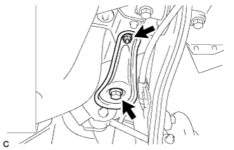
Install the rear lower suspension member stopper with the bolt and nut.
- Torque:
- Bolt
- 180 N*m { 1837 kgf*cm, 133 ft.*lbf }
- Nut
- 32 N*m { 327 kgf*cm, 24 ft.*lbf }
-
Slowly lower the jack.
-
-
TEMPORARILY TIGHTEN REAR NO. 2 SUSPENSION ARM ASSEMBLY (w/o Air Suspension)
-
Temporarily tighten the rear No. 2 suspension arm assembly to the rear suspension member with the rear suspension toe adjust cam sub-assembly, No. 2 camber adjust cam and nut.
Note
-
Insert the rear suspension toe adjust cam sub-assembly with the threaded end facing the front of the vehicle.
-
When tightening the nut, keep the toe adjust cam from rotating.
-
Fully tighten the nut after stabilizing the suspension.
-
-
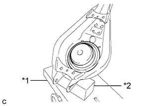
Text in Illustration *1 Jack *2 Wooden Block Support the rear No. 2 suspension arm assembly with a jack using a wooden block as shown in the illustration.
-
Install the rear lower coil spring insulator to the rear No. 2 suspension arm assembly.
-
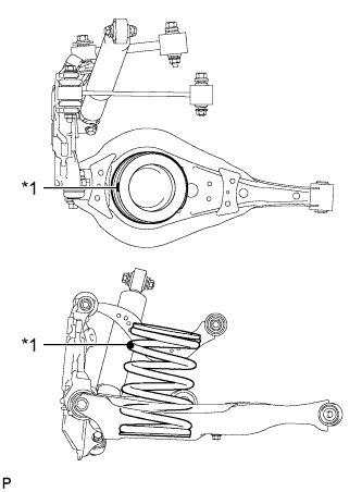
Text in Illustration *1 Identification Mark Set the rear coil spring to the rear No. 2 suspension arm assembly.
Note
Set the rear coil spring so that the identification mark is positioned as shown in the illustration.
-
Text in Illustration *1 Jack *2 Wooden Block Using a jack and wooden block, slowly jack up the rear No. 2 suspension arm assembly.
-
Install the rear No. 2 suspension arm assembly and rear coil spring with the bolt and nut.
- Torque:
- 100 N*m { 1020 kgf*cm, 74 ft.*lbf }
Note
-
Insert the bolt with the threaded end facing the front of the vehicle.
-
Since the stopper nut is used, tighten the bolt.
-
-
TEMPORARILY TIGHTEN REAR NO. 2 SUSPENSION ARM ASSEMBLY (w/ Air Suspension)
-
Temporarily tighten the rear No. 2 suspension arm assembly to the rear suspension member with the rear suspension toe adjust cam sub-assembly, No. 2 camber adjust cam and nut (A).
Note
-
Insert the rear suspension toe adjust cam sub-assembly with the threaded end facing the front of the vehicle.
-
When tightening the nut (A), keep the toe adjust cam from rotating.
-
Fully tighten the nut (A) after stabilizing the suspension.
-
-
Fully tighten the rear No. 2 suspension arm assembly to the rear axle carrier sub-assembly with the bolt (B) and nut.
- Torque:
- 100 N*m { 1020 kgf*cm, 74 ft.*lbf }
Note
-
Insert the bolt (B) with the threaded end facing the front of the vehicle.
-
Since the stopper nut is used, tighten the bolt (B).
-
Install the rear spring set plate to the rear No. 2 suspension arm assembly.
Note
When installing the rear spring set plate, first insert the positioning pin into each hole.
-
-
INSTALL REAR PNEUMATIC CYLINDER ASSEMBLY (w/ Air Suspension)
-
Install 2 new O-rings, a new plate, a new No. 2 connector to the rear pneumatic cylinder assembly.
Note
Perform this procedure when reusing the rear pneumatic cylinder assembly.
Tech Tips
For the installing procedure of the tube (type 2), refer to Precaution of the suspension control system Click here.
-
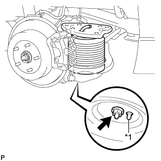
Text in Illustration *1 Positioning Pin Install the rear pneumatic cylinder assembly to the rear No. 2 suspension arm assembly with the nut.
- Torque:
- 80 N*m { 816 kgf*cm, 59 ft.*lbf }
Note
When installing the rear pneumatic cylinder assembly, first insert the positioning pin into the hole.
-
Text in Illustration *1 Jack *2 Wooden Block Jack up the rear axle assembly to install the rear pneumatic cylinder assembly, placing a wooden block underneath to avoid damage.
-
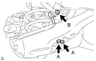
Temporarily install the rear pneumatic cylinder assembly to the body with the 3 bolts, and then fully tighten the 2 bolts (A).
- Torque:
- 50 N*m { 510 kgf*cm, 37 ft.*lbf }
-
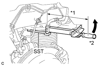
Text in Illustration *1 Fulcrum Length *2 Turn Using SST and a socket wrench, fully tighten the bolt (B).
- SST
- 09961-00950
- Torque:
- without SST
- 50 N*m { 510 kgf*cm, 37 ft.*lbf }
- with SST
- 35 N*m { 355 kgf*cm, 26 ft.*lbf }
Note
-
Use a torque wrench with a fulcrum length of 345 mm (1.13 ft.).
-
This torque value is effective when SST is parallel to the torque wrench.
-
Slowly lower the rear axle assembly.
-
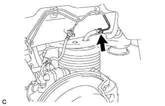
Connect the air tube to the rear pneumatic cylinder assembly.
Tech Tips
For the connecting procedure of the tube (type 2), refer to Precaution of the suspension control system Click here.
-
-
INSTALL REAR STABILIZER LINK SUB-ASSEMBLY
-
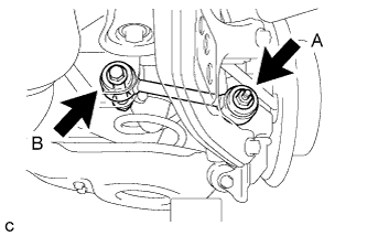
Install the rear stabilizer link sub-assembly to the rear stabilizer bar with the nut (B).
- Torque:
- 90 N*m { 918 kgf*cm, 66 ft.*lbf }
Tech Tips
If the ball joint turns together with the nut (B), use a hexagon wrench (6 mm) to hold the stud bolt.
-
Install the rear stabilizer link sub-assembly to the rear No. 2 suspension arm assembly with the 2 nuts (A).
- Torque:
- 82 N*m { 836 kgf*cm, 60 ft.*lbf }
-
-
STABILIZE SUSPENSION
-
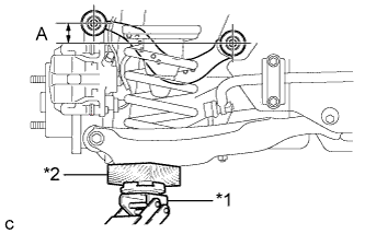
Text in Illustration *1 Jack *2 Wooden Block Jack up the rear No. 2 suspension arm assembly, placing a wooden block underneath to avoid damage. Apply load to the suspension so that the rear upper control arm assembly is positioned as shown in the illustration.
Standard length (A) 24.3 mm (0.957 in.) CAUTION:
Do not jack up the rear No. 2 suspension arm assembly too high as the vehicle may fall.
Tech Tips
-
If the rear upper control arm assembly cannot be positioned as shown in the illustration even when the rear No. 2 suspension arm assembly is jacked up, apply additional load such as by placing a weight in the luggage compartment.
-
Use the same procedure for the RH side and LH side.
-
-
-
FULLY TIGHTEN REAR NO. 1 SUSPENSION ARM ASSEMBLY
-
Using a ball joint lock nut wrench, fully tighten the bolt (B).
- Torque:
- 150 N*m { 1530 kgf*cm, 111 ft.*lbf }
Note
-
The final torque must be applied under standard vehicle height conditions.
-
Since the stopper nut is used, tighten the bolt (B).
-
Use the formula to calculate special torque values for situations where the ball joint lock nut wrench is combined with a torque wrench Click here.
-
Fully tighten the nut (A).
- Torque:
- 150 N*m { 1530 kgf*cm, 111 ft.*lbf }
Note
The final torque must be applied under standard vehicle height conditions.
-
-
FULLY TIGHTEN REAR NO. 2 SUSPENSION ARM ASSEMBLY
-
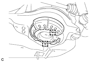
Text in Illustration *1 Matchmark Align the matchmarks on the adjust cams and rear suspension member sub-assembly.
-
Fully tighten the nut.
- Torque:
- 100 N*m { 1020 kgf*cm, 74 ft.*lbf }
Note
-
The final torque must be applied under standard vehicle height conditions.
-
When tightening the nut, keep the toe adjust cam from rotating.
-
-
INSTALL REAR SUSPENSION ARM COVER (w/o Air Suspension)
-
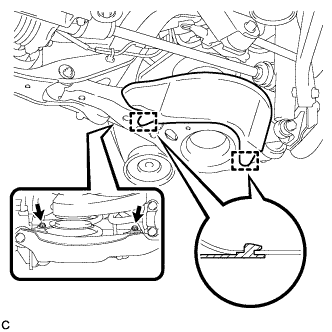
Insert the 2 guides of the rear suspension arm cover to the rear No. 2 suspension arm assembly.
-
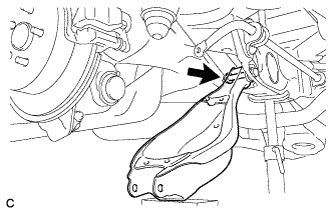
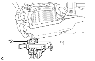
Install the rear suspension arm cover to the rear No. 2 suspension arm assembly with the 2 bolts as shown in the illustration.
- Torque:
- 12 N*m { 122 kgf*cm, 9 ft.*lbf }
Note
Make sure that the 2 guides of rear suspension arm cover are inserted.
-
-
INSTALL REAR SUSPENSION ARM COVER (w/ Air Suspension)
-
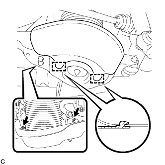
Insert the 2 guides of the rear suspension arm cover to the rear No. 2 suspension arm assembly.
-
Install the rear suspension arm cover to the rear No. 2 suspension arm assembly with the 2 bolts as shown in the illustration.
- Torque:
- 12 N*m { 122 kgf*cm, 9 ft.*lbf }
Note
Make sure that the 2 guides of rear suspension arm cover are inserted.
-
Check that the rear pneumatic cylinder cover is not deformed or collapsed inward.
-
-
INSTALL REAR WHEEL
- Torque:
- 103 N*m { 1050 kgf*cm, 76 ft.*lbf }
-
INSPECT FOR AIR LEAK (w/ Air Suspension)
-
Inspect for air leaks Click here.
-
-
INSPECT AND ADJUST REAR WHEEL ALIGNMENT
-
Inspect and adjust the rear wheel alignment Click here.
-