REAR PNEUMATIC CYLINDER INSTALLATION

Tech Tips
-
Use the same procedure for the RH side and LH side.
-
The procedure listed below is for the LH side.
-
INSTALL REAR PNEUMATIC CYLINDER COVER
-
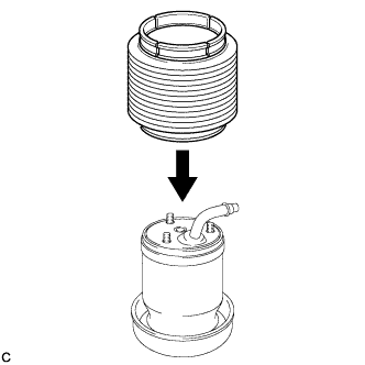
Temporarily install the rear pneumatic cylinder cover to the rear pneumatic cylinder.
Note
If the rear pneumatic cylinder cover is damaged or punctured, replace it with a new one.
-
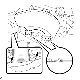
Set the rear pneumatic cylinder cover in the installing position as shown in the illustration.
-
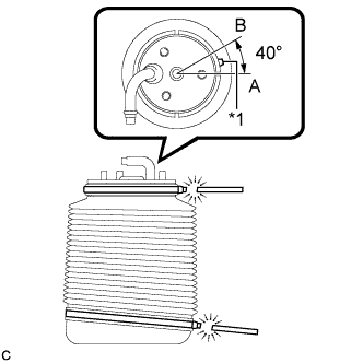
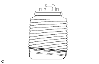
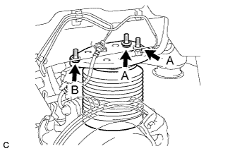
Text in Illustration *1 Clamping Joint Install the rear pneumatic cylinder cover to the rear pneumatic cylinder with 2 new rear height control cover bands.
Note
Position the clamping joints between points A and B as shown in the illustration.
-
Cut the surplus of the rear height control cover bands as shown in the illustration.
-
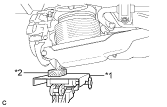
Temporarily install the pneumatic chamber bracket to the rear pneumatic cylinder with the 3 nuts.
-
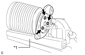
Text in Illustration *1 Wooden Block Using a wooden block, hold the pneumatic chamber bracket between aluminium plates in a vise as shown in the illustration.
-
Fully tighten the 3 nuts.
- Torque:
- 37 N*m { 377 kgf*cm, 27 ft.*lbf }
-
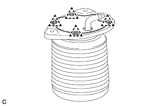
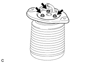
Install the bracket cover to the pneumatic chamber bracket with the 4 clips.
-
Check that the rear pneumatic cylinder cover is not deformed or collapsed inward.
-
-
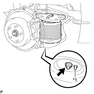
INSTALL HEIGHT CONTROL PLUG
-
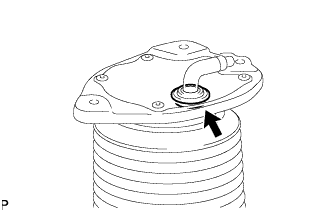
Install the height control plug to the rear pneumatic cylinder assembly.
-
-
INSTALL REAR SPRING SET PLATE
-
Install the rear spring set plate to the rear No. 2 suspension arm assembly.
Note
When installing the rear spring set plate, first insert the positioning pin into each hole.
-
-
INSTALL REAR PNEUMATIC CYLINDER ASSEMBLY
-
Install 2 new O-rings, a new plate, a new No. 2 connector to the rear pneumatic cylinder assembly.
Note
Perform this procedure when reusing the rear pneumatic cylinder assembly.
Tech Tips
For the installing procedure of the tube (type 2), refer to Precaution of the suspension control system Click here.
-
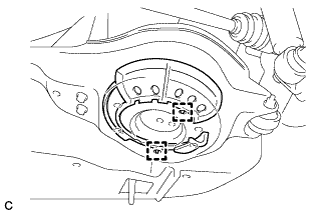
Text in Illustration *1 Positioning Pin Install the rear pneumatic cylinder assembly to the rear No. 2 suspension arm assembly with the nut.
- Torque:
- 80 N*m { 816 kgf*cm, 59 ft.*lbf }
Note
When installing the rear pneumatic cylinder assembly, first insert the positioning pin into the hole.
-
Text in Illustration *1 Jack *2 Wooden Block Jack up the rear axle assembly to install the rear pneumatic cylinder assembly, placing a wooden block underneath to avoid damage.
-
Temporarily install the rear pneumatic cylinder assembly to the body with the 3 bolts, and then fully tighten the 2 bolts (A).
- Torque:
- 50 N*m { 510 kgf*cm, 37 ft.*lbf }
-
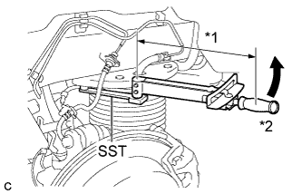
Text in Illustration *1 Fulcrum Length *2 Turn Using SST and a socket wrench, fully tighten the bolt (B).
- SST
- 09961-00950
- Torque:
- without SST
- 50 N*m { 510 kgf*cm, 37 ft.*lbf }
- with SST
- 35 N*m { 355 kgf*cm, 26 ft.*lbf }
Note
-
Use a torque wrench with a fulcrum length of 345 mm (1.13 ft.).
-
This torque value is effective when SST is parallel to the torque wrench.
-
Slowly lower the rear axle assembly.
-
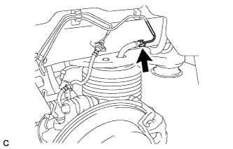
Connect the air tube to the rear pneumatic cylinder assembly.
Tech Tips
For the connecting procedure of the tube (type 2), refer to Precaution of the suspension control system Click here.
-
-
INSTALL REAR SUSPENSION ARM COVER
-
Insert the 2 guides of the rear suspension arm cover to the rear No. 2 suspension arm assembly.
-
Install the rear suspension arm cover to the rear No. 2 suspension arm assembly with the 2 bolts as shown in the illustration.
- Torque:
- 12 N*m { 122 kgf*cm, 9 ft.*lbf }
Note
Make sure that the 2 guides of rear suspension arm cover are inserted.
-
Check that the rear pneumatic cylinder cover is not deformed or collapsed inward.
-
-
INSTALL REAR WHEEL
- Torque:
- 103 N*m { 1050 kgf*cm, 76 ft.*lbf }
-
INSPECT FOR AIR LEAK
-
Inspect for air leaks Click here.
-