PNEUMATIC TANK INSTALLATION

-
CONNECT NO. 1 HEIGHT CONTROL TUBE
-
Coat 2 new O-rings with MP grease No. 2.
-
Install the new O-rings to the No. 1 height control tube.
-
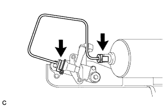
Install the No. 1 height control tube to the pneumatic tank sub-assembly.
Tech Tips
For the connecting procedure of the tube (type 3), refer to Precaution of the suspension control system Click here.
-
Lock the 2 holders.
-
-
INSTALL PNEUMATIC TANK WITH TUBE ASSEMBLY
-
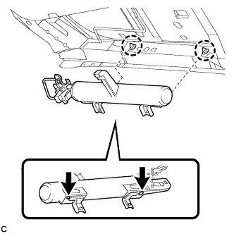
Temporarily install the pneumatic tank with tube assembly brackets to the 2 clamps.
-
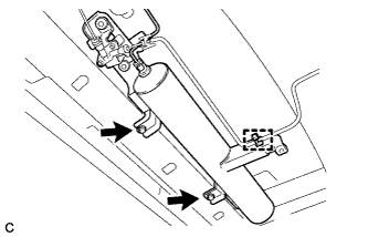
Install the pneumatic tank with tube assembly with the 2 bolts.
- Torque:
- 29 N*m { 296 kgf*cm, 21 ft.*lbf }
-
Engage the height control tube to the clamp.
-
Coat 2 new O-rings with MP grease No. 2.
-
Install the new O-rings and a new plate to the pneumatic tank with tube assembly.
-
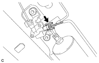
Install the height control tube to the pneumatic tank with tube assembly.
Tech Tips
For the connecting procedure of the tube (type 2), refer to Precaution of the suspension control system Click here.
-
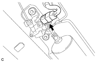
Connect the connector.
-
-
INSTALL ENGINE SERVICE COVER STAY
-
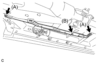
Install the engine service cover stay with the 3 bolts.
- Torque:
- Bolt (A)
- 7.5 N*m { 76 kgf*cm, 66 in.*lbf }
- Bolt (B)
- 29 N*m { 296 kgf*cm, 21 ft.*lbf }
Note
Tighten the 2 bolts (A) first, and then the bolt (B).
-
-
CONNECT CABLE TO NEGATIVE BATTERY TERMINAL
Note
When disconnecting the cable, some systems need to be initialized after the cable is reconnected Click here.
-
INSTALL REAR DECK FLOOR BOX
-

Install the rear deck floor box with the 3 clips.
-
-
PERFORM INITIALIZATION
-
Perform initialization Click here.
-
-
INSPECT FOR AIR LEAK
-
Inspect for air leaks Click here.
-
-
INSTALL FRONT FLOOR COVER RH