AIR SUSPENSION SYSTEM, Diagnostic DTC:C1762

| DTC Code | DTC Name |
|---|---|
| C1762 | Continuous Electric Current to Exhaust Solenoid |
DESCRIPTION
The exhaust valve built into the height control compressor assembly opens to discharge compressed air from the pneumatic cylinders into the atmosphere according to the signal from the suspension control ECU.
| DTC No. | DTC Detection Condition | Trouble Area |
|---|---|---|
| C1762 | Control to lower the vehicle is on continuously for 3 minutes. |
|
INSPECTION PROCEDURE
Note
-
Before performing troubleshooting, inspect the connectors of related circuits.
-
If DTC C1782 (Power Source Voltage Malfunction) is output at the same time, perform troubleshooting for C1782 first Click here.
-
Before replacing the suspension control ECU, perform all of the following again: 1) symptom simulation Click here; 2) DTC inspection Click here; and 3) Intelligent tester inspection (Data List or Active Test) Click here. If no malfunctions are found in other areas, replace the suspension control ECU.
-
If the suspension control ECU is replaced, the vehicle height offset calibration and registration of vehicle identification information must be performed Click here and Click here
PROCEDURE
-
CUSTOMER PROBLEM ANALYSIS
-
Ask the customer about the vehicle and usage conditions when the DTC was stored.
Tech Tips
DTC C1762 can be stored under unusual vehicle or usage conditions.
Points to confirm
-
Confirm if there were any foreign objects caught between the body and tires.
-
Confirm if the vehicle has been driven on an unpaved surface or with a wheel not contacting the ground.
-
Confirm if the vehicle height mode has been continuously changed using the height control switch, causing the vehicle to raise and lower repeatedly.
-
NEXT 
-
-
CHECK DTC
-
Clear the DTC Click here.
-
Turn the power switch on (READY) and wait for 3 minutes or more.
-
Select luggage mode.
-
Select HI mode.
-
Check the DTC Click here.
Result Result Proceed to DTC C1762 is output A DTC C1762 is not output B DTC C1762 and other DTCs are output C
B 
END (C1762 WAS OUTPUT DUE TO UNUSUAL VEHICLE OR USAGE CONDITION)
C
GO TO DTC CHART Click here
A
-
-
INSPECT AIR TUBE (AIR TUBE FOR CLOG)
-
Inspect the air tubes for clogs Click here.
OK No clogs are found in the air tubes.
NG
REPAIR OR REPLACE AIR TUBE
OK
-
-
INSPECT HEIGHT CONTROL VALVE NO. 1
-
Turn the power switch off.
-
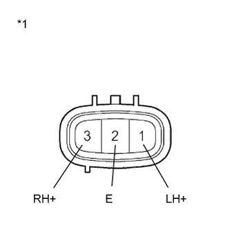
Text in Illustration *1 Component without harness connected
(Height Control Valve No. 1)
Disconnect the height control valve No. 1 connector.
-
Measure the resistance according to the values in the table below.
Standard resistance Tester Connection Condition Specified Condition 3 (RH+) - 2 (E) 15 to 25°C (59 to 77°F) 10 to 14 Ω 1 (LH+) - 2 (E) 15 to 25°C (59 to 77°F) 10 to 14 Ω -
Check the front RH valve.
-
Connect a positive (+) lead from the battery to terminal 3 (RH+) and a negative (-) lead to terminal 2 (E).
-
Check the operating sound of the height control valve No. 1.
OK It makes an operating sound (click).
-
-
Check the front LH valve.
-
Connect a positive (+) lead from the battery to terminal 1 (LH+) and a negative (-) lead to terminal 2 (E).
-
Check the operating sound of the height control valve No. 1.
OK It makes an operating sound (click).
-
NG
REPLACE HEIGHT CONTROL VALVE NO. 1 Click here
OK
-
-
INSPECT HEIGHT CONTROL VALVE NO. 2
-
Turn the power switch off.
-
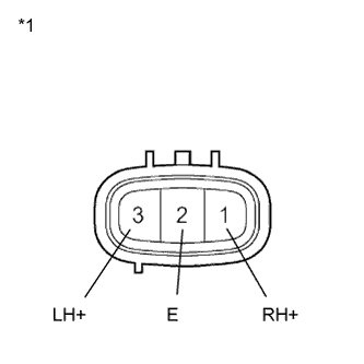
Text in Illustration *1 Component without harness connected
(Height Control Valve No. 2)
Disconnect the height control valve No. 2 connector.
-
Measure the resistance according to the values in the table below.
Standard resistance Tester Connection Condition Specified Condition 1 (RH+) - 2 (E) 15 to 25°C (59 to 77°F) 10 to 14 Ω 3 (LH+) - 2 (E) 15 to 25°C (59 to 77°F) 10 to 14 Ω -
Check the rear RH valve.
-
Connect a positive (+) lead from the battery to terminal 1 (RH+) and a negative (-) lead to terminal 2 (E).
-
Check the operating sound of the height control valve No. 2.
OK It makes an operating sound (click).
-
-
Check the rear LH valve.
-
Connect a positive (+) lead from the battery to terminal 3 (LH+) and a negative (-) lead to terminal 2 (E).
-
Check the operating sound of the height control valve No. 2.
OK It makes an operating sound (click).
-
NG
REPLACE HEIGHT CONTROL VALVE NO. 2 Click here
OK
-
-
INSPECT HEIGHT CONTROL COMPRESSOR ASSEMBLY (EXHAUST VALVE)
-
Turn the power switch off.
-
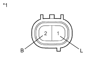
Text in Illustration *1 Component without harness connected
(Exhaust Valve)
Disconnect the exhaust valve connector.
-
Measure the resistance according to the value(s) in the table below.
Standard resistance Tester Connection Condition Specified Condition 2 (B) - 1 (L) 15 to 25°C (59 to 77°F) 10 to 14 Ω -
Inspect if the exhaust valve is stuck:
-
Connect a positive (+) lead from the battery to terminal 2 (B) and a negative (-) lead to terminal 1 (L).
-
Check the operating sound of the exhaust valve.
OK It makes an operating sound (click).
-
NG
REPLACE HEIGHT CONTROL COMPRESSOR ASSEMBLY Click here
OK
-
-
INSPECT PNEUMATIC W/TUBE TANK ASSEMBLY (LOW PRESSURE TANK VALVE)
-
Turn the power switch off.
-

Text in Illustration *1 Component without harness connected
(Low Pressure Tank Valve)
Disconnect the low pressure tank valve connector.
-
Measure the resistance according to the value(s) in the table below.
Standard resistance Tester Connection Condition Specified Condition 2 (B) - 1 (L) 15 to 25°C (59 to 77°F) 10 to 14 Ω -
Inspect if the low pressure tank valve is stuck :
-
Connect a positive (+) lead from the battery to terminal 2 (B) and a negative (-) lead to terminal 1 (L).
-
Check the operating sound of the low pressure tank valve.
OK It makes an operating sound (click). Result Condition Proceed to OK (for LHD) A OK (for RHD) B NG C
-
B
REPLACE SUSPENSION CONTROL ECU (for RHD) Click here
C
REPLACE PNEUMATIC W/TUBE TANK ASSEMBLY Click here
A 
REPLACE SUSPENSION CONTROL ECU (for LHD) Click here
-