REAR AXLE CARRIER INSTALLATION

Tech Tips
-
Use the same procedure for the RH side and LH side.
-
The procedure listed below is for the LH side.
-
TEMPORARILY TIGHTEN REAR AXLE CARRIER SUB-ASSEMBLY
-
Hold the rear axle carrier sub-assembly between aluminium plates in a vise.
Note
Do not overtighten the vise.
-
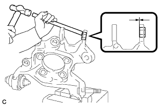
Using a brass bar and a hammer, push out the bushing until it is positioned as shown in the illustration.
Tech Tips
Pushing out the bushing makes it easier to install the rear axle carrier sub-assembly.
-
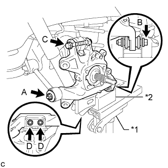
Text in Illustration *1 Jack *2 Wooden Block Temporarily tighten the rear axle carrier sub-assembly to the rear No. 1 suspension arm assembly with the spacer and nut (A).
Note
Fully tighten the nut (A) after stabilizing the suspension.
-
Fully tighten the rear axle carrier sub-assembly to the rear No. 2 suspension arm assembly with the bolt (B) and nut.
- Torque:
- 100 N*m { 1020 kgf*cm, 74 ft.*lbf }
Note
-
Insert the bolt with the threaded end facing the front side of the vehicle.
-
Since the stopper nut is used, tighten the bolt (B).
-
Fully tighten the rear axle carrier sub-assembly to the rear upper control arm assembly with the bolt (C) and nut.
- Torque:
- 145 N*m { 1479 kgf*cm, 107 ft.*lbf }
Note
-
Insert the bolt with the threaded end facing the rear side of the vehicle.
-
Since the stopper nut is used, tighten the bolt (C).
-
Fully tighten the rear axle carrier sub-assembly to the rear lower shock absorber bracket sub-assembly with the 2 bolts (D).
- Torque:
- 100 N*m { 1020 kgf*cm, 74 ft.*lbf }
-
Slowly lower the rear No. 2 suspension arm assembly.
-
-
TEMPORARILY TIGHTEN PARKING BRAKE ASSEMBLY
-
Temporarily tighten the parking brake assembly to the rear axle carrier sub-assembly with the nut.
Note
-
Do not twist the parking brake cable when installing the parking brake assembly.
-
Fully tighten the nut after installing the rear trailing arm assembly.
-
-
-
INSTALL REAR TRAILING ARM ASSEMBLY
-
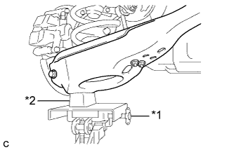
Text in Illustration *1 Jack *2 Wooden Block Using a jack and wooden block, jack up the rear No. 2 suspension arm assembly to replicate standard vehicle height conditions.
CAUTION:
Do not jack up the rear No. 2 suspension arm assembly too high as the vehicle may fall.
-
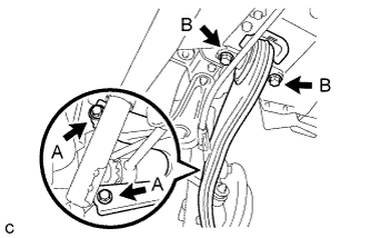
Install the rear trailing arm assembly to the rear axle carrier sub-assembly with the 2 bolts (A) and 2 washers.
- Torque:
- 150 N*m { 1530 kgf*cm, 111 ft.*lbf }
-
Install the rear trailing arm assembly to the body with the 2 bolts (B).
- Torque:
- 150 N*m { 1530 kgf*cm, 111 ft.*lbf }
-
Slowly lower the rear No. 2 suspension arm assembly.
-
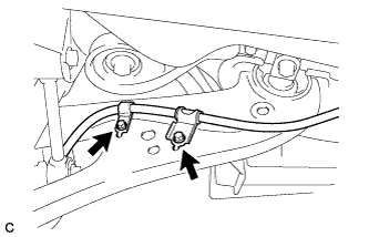
Install the No. 3 parking brake cable assembly to the rear trailing arm assembly with the 2 bolts.
- Torque:
- 19 N*m { 192 kgf*cm, 14 ft.*lbf }
Note
Do not twist the No. 3 parking brake cable assembly when installing it.
-
-
FULLY TIGHTEN PARKING BRAKE ASSEMBLY
-
Fully tighten the nut.
- Torque:
- 160 N*m { 1632 kgf*cm, 118 ft.*lbf }
-
-
INSTALL REAR AXLE HUB AND BEARING ASSEMBLY
-
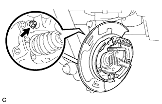
Text in Illustration *1 Matchmark Align the matchmarks on the rear drive shaft assembly and rear axle hub and bearing assembly, and then insert the rear drive shaft assembly to the rear axle hub and bearing assembly.
-
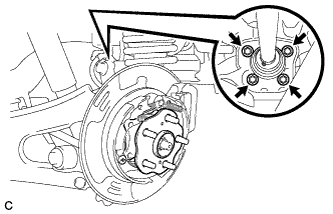
Install the rear axle hub and bearing assembly to the rear axle carrier sub-assembly with the 4 bolts.
- Torque:
- 125 N*m { 1275 kgf*cm, 92 ft.*lbf }
-
-
INSTALL REAR SPEED SENSOR
-
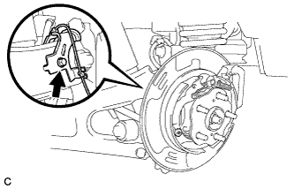
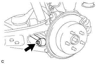
Install the rear speed sensor to the rear trailing arm assembly with the bolt.
- Torque:
- 8.0 N*m { 82 kgf*cm, 71 in.*lbf }
Note
Do not twist the rear speed sensor when installing it.
-
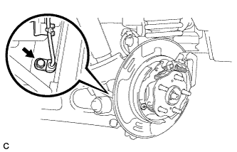
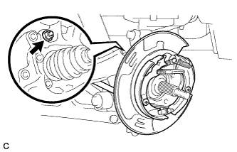
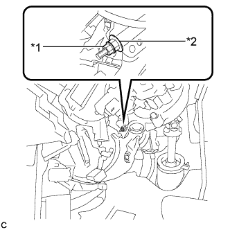
Install the rear speed sensor to the rear axle carrier sub-assembly with the bolt.
- Torque:
- 8.0 N*m { 82 kgf*cm, 71 in.*lbf }
Note
-
Prevent foreign matter from attaching to the rear speed sensor tip.
-
Do not file the rear speed sensor installation hole or surface because the gap between the magnet rotor and rear speed sensor is important.
-
Do not twist or apply excessive force to the rear speed sensor during installation to prevent it from being damaged.
-
Do not twist the rear speed sensor when installing it.
-
-
INSTALL REAR DISC
-
Text in Illustration *1 Matchmark Align the matchmarks and install the rear disc.
Note
When replacing the rear disc with a new one, select the installation position where the rear disc has minimal runout.
-
-
INSTALL PARKING BRAKE SHOE ADJUSTING HOLE PLUG
-
Install the parking brake shoe adjusting hole plug.
-
-
INSTALL REAR DISC BRAKE CALIPER ASSEMBLY
-
Install the rear disc brake caliper assembly to the rear axle carrier sub-assembly with the 2 bolts.
- Torque:
- 78 N*m { 799 kgf*cm, 58 ft.*lbf }
-
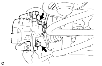
Install the rear flexible hose to the rear upper control arm assembly with the bolt.
- Torque:
- 19 N*m { 192 kgf*cm, 14 ft.*lbf }
Note
-
Do not twist the rear flexible hose when installing it.
-
Do not damage the rear flexible hose when reassembling it.
-
If the rear flexible hose is damaged, replace it with a new one.
-
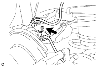
Install the rear flexible hose to the bracket with a new clip.
Note
-
Install the clip as far as it will go.
-
Do not twist the rear flexible hose when installing it.
-
-
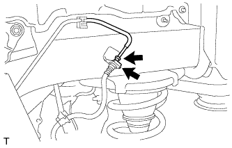
Using a union nut wrench, connect the brake line to the rear flexible hose.
- Torque:
- 15 N*m { 155 kgf*cm, 11 ft.*lbf }
Note
-
Do not bend or damage the brake line.
-
Do not allow any foreign matter such as dirt and dust to enter the brake line.
-
Use the formula to calculate special torque values for situations where the union nut wrench is combined with a torque wrench Click here.
-
-
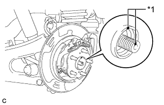
INSTALL REAR AXLE SHAFT NUT
-
Clean the threaded parts on the rear drive shaft assembly and a new rear axle shaft nut using a non-residue solvent.
Note
-
Be sure to perform this work for a new rear drive shaft assembly.
-
Keep the threaded parts free of oil and foreign matter.
-
-
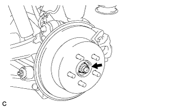
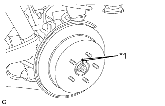
While applying the parking brakes, install the new rear axle shaft nut.
- Torque:
- 294 N*m { 2998 kgf*cm, 217 ft.*lbf }
-
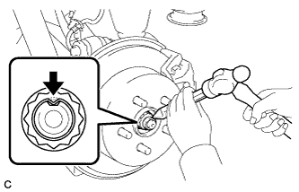
Using a chisel and a hammer, stake the rear axle shaft nut.
-
-
CONNECT AIR TUBE (w/ Air Suspension)
-
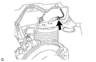
Install 2 new O-rings, a new plate and a new No. 2 connector, and then connect the air tube to the rear pneumatic cylinder assembly.
Tech Tips
For the installing and connecting procedure of the tube (type 2), refer to Precaution of the suspension control system Click here.
-
-
ADJUST PARKING BRAKE SHOE CLEARANCE AND PARKING BRAKE PEDAL TRAVEL (for LHD)
-
Remove the No. 1 instrument panel under cover sub-assembly Click here.
-
Completely release the parking brake pedal.
-
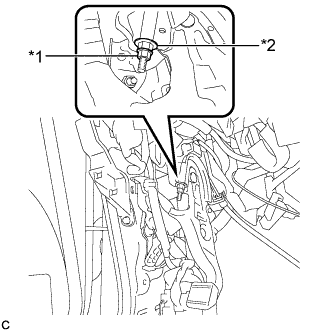
Text in Illustration *1 Lock Nut *2 Adjusting Nut Loosen the lock nut and the adjusting nut to completely release the parking brake cable.
-
Remove the rear wheels.
-
Temporarily install the hub nuts to the hub bolts.
Tech Tips
Securely install the hub nuts to the rear disc.
-
Remove the parking brake shoe adjusting hole plug.
-
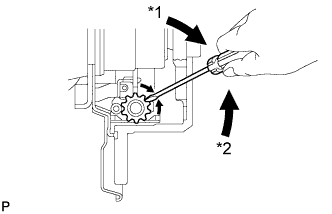
Text in Illustration *1 Expand *2 Contract Turn the shoe adjuster and expand the shoe until the disc locks.
-
Turn and contract the shoe adjuster until the disc can rotate smoothly.
Standard Returns 8 notches. -
Check that there is no brake drag against the shoe.
-
Install the parking brake shoe adjusting hole plug.
-
Turn the adjusting nut until the parking brake pedal travel is corrected to be within the specified range.
Parking brake pedal travel 7 to 10 notches at 300 N (31 kgf, 67.5 lbf) -
Text in Illustration *1 Lock Nut *2 Adjusting Nut Using a wrench or an equivalent tool, hold the adjusting nut and tighten the lock nut.
- Torque:
- 7.0 N*m { 71 kgf*cm, 62 in.*lbf }
-
Operate the parking brake pedal 3 to 4 times, and check the parking brake pedal travel.
-
Check that there is no brake drag against the shoe.
-
Remove the hub nuts from the hub bolts.
-
Install the rear wheels.
- Torque:
- 103 N*m { 1050 kgf*cm, 76 ft.*lbf }
-
Install the No. 1 instrument panel under cover sub-assembly Click here.
-
-
ADJUST PARKING BRAKE SHOE CLEARANCE AND PARKING BRAKE PEDAL TRAVEL (for RHD)
-
Remove the No. 1 instrument panel under cover sub-assembly Click here.
-
Completely release the parking brake pedal.
-
Text in Illustration *1 Lock Nut *2 Adjusting Nut Loosen the lock nut and the adjusting nut to completely release the parking brake cable.
-
Remove the rear wheels.
-
Temporarily install the hub nuts to the hub bolts.
Tech Tips
Securely install the hub nuts to the rear disc.
-
Remove the shoe adjusting hole plug.
-
Text in Illustration *1 Expand *2 Contract Turn the shoe adjuster and expand the shoe until the disc locks.
-
Turn and contract the shoe adjuster until the disc can rotate smoothly.
Standard Returns 8 notches. -
Check that there is no brake drag against the shoe.
-
Install the shoe adjusting hole plug.
-
Turn the adjusting nut until the parking brake pedal travel is corrected to be within the specified range.
Parking brake pedal travel 7 to 10 notches at 300 N (31 kgf, 67.5 lbf) -
Text in Illustration *1 Lock Nut *2 Adjusting Nut Using a wrench or an equivalent tool, hold the adjusting nut and tighten the lock nut.
- Torque:
- 7.0 N*m { 71 kgf*cm, 62 in.*lbf }
-
Operate the parking brake pedal 3 to 4 times, and check the parking brake pedal travel.
-
Check that there is no brake drag against the shoe.
-
Remove the hub nuts from the hub bolts.
-
Install the rear wheels.
- Torque:
- 103 N*m { 1050 kgf*cm, 76 ft.*lbf }
-
Install the No. 1 instrument panel under cover sub-assembly Click here.
-
-
BLEED BRAKE SYSTEM
-
Bleed brake line.
-
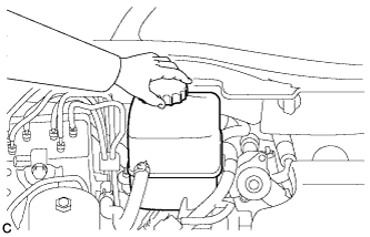
Remove the brake master cylinder reservoir filler cap assembly.
-
Add brake fluid into the reservoir between MAX and MIN level on the brake fluid reservoir.
Brake fluid SAE J1703 or FMVSS No. 116 DOT3 -
Connect the intelligent tester to the DLC3 and turn the power switch on (IG).
-
Turn the intelligent tester on and enter the following menus: Chassis / ABS/VSC/TRC / Utility / Air Bleeding.
-
Select the "Usual air bleeding / All Line" and bleed brake line according to the intelligent tester display.
-
After air bleeding, tighten each bleeder plug.
- Torque:
- front bleeder plug
- 8.3 N*m { 85 kgf*cm, 73 in.*lbf }
- rear bleeder plug
- 11 N*m { 110 kgf*cm, 8 ft.*lbf }
-
-
Clear the DTCs Click here.
-
Turn the intelligent tester off and turn the power switch off.
-
Inspect for brake fluid leaks.
-
Adjust the brake fluid level in the reservoir Click here.
-
-
STABILIZE SUSPENSION
-
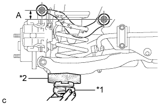
Text in Illustration *1 Jack *2 Wooden Block Jack up the rear No. 2 suspension arm assembly, placing a wooden block underneath to avoid damage. Apply load to the suspension so that the rear upper control arm assembly is positioned as shown in the illustration.
Standard length (A) 24.3 mm (0.957 in.) CAUTION:
Do not jack up the rear No. 2 suspension arm assembly too high as the vehicle may fall.
Tech Tips
-
If the rear upper control arm assembly cannot be positioned as shown in the illustration even when the rear No. 2 suspension arm assembly is jacked up, apply additional load such as by placing a weight in the luggage compartment.
-
Use the same procedure for the RH side and LH side.
-
-
-
FULLY TIGHTEN REAR AXLE CARRIER SUB-ASSEMBLY
-
Fully tighten the nut.
- Torque:
- 150 N*m { 1530 kgf*cm, 111 ft.*lbf }
Note
The final torque must be applied under standard vehicle height conditions.
-
-
INSTALL REAR SUSPENSION ARM COVER (w/o Air Suspension)
-
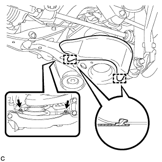
Insert the 2 guides of the rear suspension arm cover to the rear No. 2 suspension arm assembly.
-
Install the rear suspension arm cover to the rear No. 2 suspension arm assembly with the 2 bolts as shown in the illustration.
- Torque:
- 12 N*m { 122 kgf*cm, 9 ft.*lbf }
Note
Make sure that the 2 guides of rear suspension arm cover are inserted.
-
-
INSTALL REAR SUSPENSION ARM COVER (w/ Air Suspension)
-
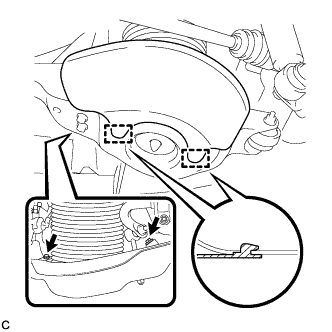
Insert the 2 guides of the rear suspension arm cover to the rear No. 2 suspension arm assembly.
-
Install the rear suspension arm cover to the rear No. 2 suspension arm assembly with the 2 bolts as shown in the illustration.
- Torque:
- 12 N*m { 122 kgf*cm, 9 ft.*lbf }
Note
Make sure that the 2 guides of rear suspension arm cover are inserted.
-
Check that the rear pneumatic cylinder cover is not deformed or collapsed inward.
-
-
INSTALL REAR WHEEL
- Torque:
- 103 N*m { 1050 kgf*cm, 76 ft.*lbf }
-
INSPECT FOR AIR LEAK (w/ Air Suspension)
-
Inspect for air leaks Click here.
-
-
INSPECT AND ADJUST REAR WHEEL ALIGNMENT
-
Inspect and adjust the rear wheel alignment Click here.
-
-
CHECK SPEED SENSOR SIGNAL
-
Check for the speed sensor signal Click here.
-