REAR AXLE HUB REMOVAL

Note
When the brake pedal is first depressed after replacing the brake pads or pushing back the disc brake piston, DTC C1341, C1342, C1343 and/or C1344 may be stored. As there is no malfunction, clear the DTC(s).
Tech Tips
-
Use the same procedure for the RH side and LH side.
-
The procedure listed below is for the LH side.
-
PRECAUTION (w/ Air Suspension)
-
REMOVE REAR WHEEL
-
REMOVE REAR AXLE SHAFT NUT (for AWD)
-
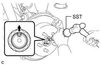
Using SST and a hammer, release the staked part of the rear axle shaft nut.
- SST
- 09930-00010
Note
Loosen the staked part of the nut completely, otherwise the threads of the rear drive shaft assembly may be damaged.
-
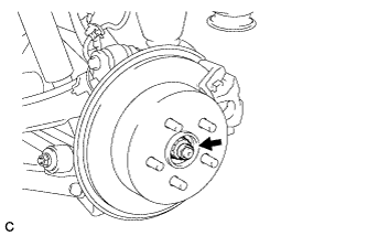
While applying the parking brakes, remove the rear axle shaft nut from the rear drive shaft assembly.
-
-
REMOVE REAR SUSPENSION ARM COVER (w/o Air Suspension)
-
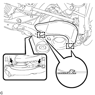
Remove the 2 bolts.
-
Disengage the 2 guides and remove the rear suspension arm cover from the rear No. 2 suspension arm assembly.
-
-
REMOVE REAR SUSPENSION ARM COVER (w/ Air Suspension)
-
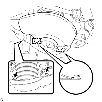
Remove the 2 bolts.
-
Disengage the 2 guides and remove the rear suspension arm cover from the rear No. 2 suspension arm assembly.
-
-
SEPARATE REAR DISC BRAKE CALIPER ASSEMBLY
-
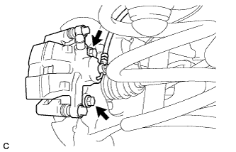
Remove the 2 bolts, and separate the rear disc brake caliper assembly.
Note
Use wire or an equivalent tool to keep the brake caliper from hanging down by the flexible hose.
-
-
REMOVE PARKING BRAKE SHOE ADJUSTING HOLE PLUG
-
Remove the parking brake shoe adjusting hole plug.
-
-
REMOVE REAR DISC
-
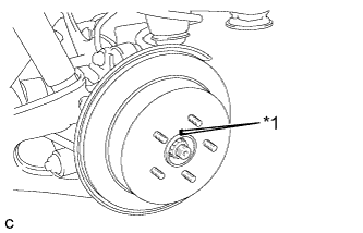
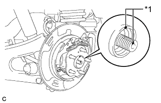
Text in Illustration *1 Matchmark Put matchmarks on the rear disc and the axle hub.
-
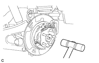
Release the parking brake and remove the rear disc.
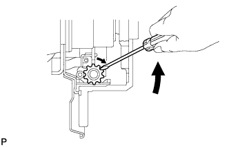
Tech Tips
If the disc can not be removed easily, use a screwdriver to turn the shoe adjuster as shown in the illustration in order to contract the parking brake shoes.
-
-
SEPARATE REAR SPEED SENSOR WIRE (for 2WD)
-
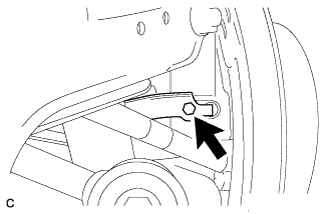
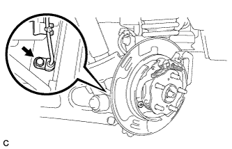
Remove the bolt and No. 1 bracket.
-
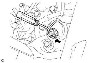
Using a screwdriver, disconnect the connector from the rear speed sensor.
Note
Be careful not to damage the rear speed sensor.
-
-
SEPARATE REAR SPEED SENSOR (for AWD)
-
Remove the bolt and separate the rear speed sensor from the rear axle carrier sub-assembly.
Note
-
Prevent foreign matter from attaching to the rear speed sensor tip.
-
Clean the rear speed sensor installation hole and the contact surfaces every time the rear speed sensor is removed.
-
Do not twist or apply excessive force to the rear speed sensor during removal from the rear axle carrier sub-assembly to prevent it from being damaged.
-
-
-
REMOVE REAR AXLE HUB AND BEARING ASSEMBLY (for 2WD)
-

Remove the 4 bolts and the rear axle hub and bearing assembly from the rear axle carrier sub-assembly.
-
-
REMOVE REAR AXLE HUB AND BEARING ASSEMBLY (for AWD)
-
Text in Illustration *1 Matchmark Put matchmarks on the rear drive shaft assembly and rear axle hub and bearing assembly.
-
Using a plastic hammer, separate the rear drive shaft assembly from the rear axle hub and bearing assembly.
Tech Tips
If it is difficult to separate, tap the end of the rear drive shaft assembly using a brass bar and a hammer.
-
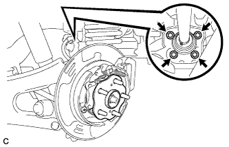
Remove the 4 bolts and the rear axle hub and bearing assembly from the rear axle carrier sub-assembly.
-