HYBRID TRANSAXLE SIDE GEAR OIL SEAL REPLACEMENT

Tech Tips
-
Use the same procedure for the RH side and LH side.
-
The procedure listed below is for the LH side.
-
PRECAUTION (w/ Air Suspension)
Note
Be sure to read Precaution thoroughly before servicing Click here.
-
REMOVE REAR WHEEL
-
DRAIN HYBRID TRANSAXLE FLUID
-
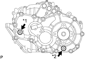
Text in Illustration *1 Filler Plug *2 Drain Plug Using a hexagon socket wrench 10 mm, remove the filler plug and gasket.
-
Using a hexagon socket wrench 10 mm, remove the drain plug and gasket.
-
Using a hexagon socket wrench 10 mm, install the drain plug and a new gasket.
- Torque:
- 39 N*m { 398 kgf*cm, 29 ft.*lbf }
-
-
REMOVE TAIL EXHAUST PIPE ASSEMBLY (for RH Side)
-
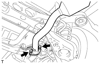
Remove the 2 bolts and 2 compression springs.
-
Remove the tail exhaust pipe assembly from the 2 exhaust pipe supports.
-
Remove the gasket from the center exhaust pipe assembly.
-
-
SEPARATE REAR SPEED SENSOR
-
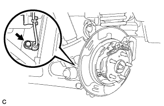
Remove the bolt and separate the rear speed sensor from the rear axle carrier sub-assembly.
Note
-
Prevent foreign matter from attaching to the rear speed sensor tip.
-
Clean the rear speed sensor installation hole and the contact surfaces every time the rear speed sensor is removed.
-
Do not twist or apply excessive force to the rear speed sensor during removal from the rear axle carrier sub-assembly to prevent it from being damaged.
-
-
-
REMOVE REAR AXLE SHAFT NUT
-
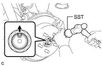
Using SST and a hammer, release the staked part of the rear axle shaft nut.
- SST
- 09930-00010
Note
Loosen the staked part of the nut completely, otherwise the threads of the rear drive shaft assembly may be damaged.
-
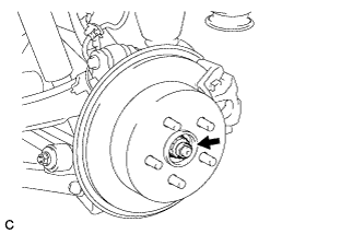
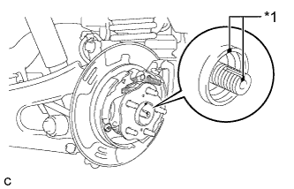
While applying the parking brakes, remove the rear axle shaft nut from the rear drive shaft assembly.
-
-
REMOVE REAR SUSPENSION ARM COVER (w/o Air Suspension)
-
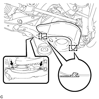
Remove the 2 bolts.
-
Disengage the 2 guides and remove the rear suspension arm cover from the rear No. 2 suspension arm assembly.
-
-
REMOVE REAR SUSPENSION ARM COVER (w/ Air Suspension)
-
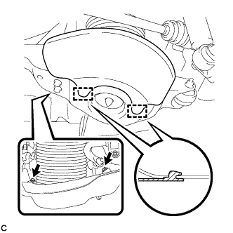
Remove the 2 bolts.
-
Disengage the 2 guides and remove the rear suspension arm cover from the rear No. 2 suspension arm assembly.
-
-
REMOVE REAR DRIVE SHAFT ASSEMBLY
-
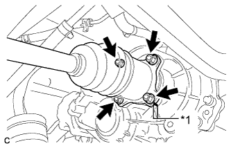
Text in Illustration *1 Matchmark Put matchmarks on the rear drive shaft assembly and differential side gear shaft.
-
Remove the 4 nuts, washers and rear drive shaft assembly.
-
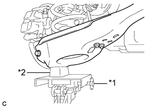
Text in Illustration *1 Jack *2 Wooden Block Using a jack and wooden block, jack up the rear No. 2 suspension arm assembly to replicate standard vehicle height conditions.
Note
Do not jack up the rear No. 2 suspension arm assembly too high as the vehicle may fall.
-
Text in Illustration *1 Matchmark Put matchmarks on the rear drive shaft assembly and rear axle hub and bearing assembly.
-
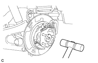
Using a plastic hammer, separate the rear drive shaft assembly from the rear axle hub and bearing assembly.
Tech Tips
If it is difficult to separate, tap the end of the rear drive shaft assembly using a brass bar and a hammer.
-
Push the rear drive shaft inboard joint assembly toward the outside of the vehicle and remove the rear drive shaft assembly LH from the differential side gear shaft sub-assembly.
-
-
REMOVE DIFFERENTIAL SIDE GEAR SHAFT SUB-ASSEMBLY
-
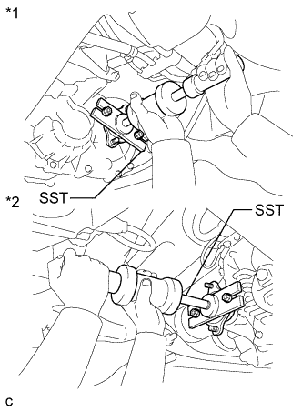
Text in Illustration *1 LH Side *2 RH Side Using SST, remove the side gear shaft.
- SST
- 09520-24010 ( 09520-04010, 09520-32040 )
Note
Do not damage the oil seal.
-
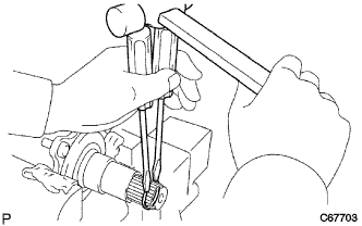
Using 2 screwdrivers and a hammer, remove the side gear shaft snap ring.
-
-
REMOVE REAR TRANSAXLE SIDE GEAR OIL SEAL
-
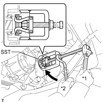
Text in Illustration *1 Hold *2 Turn LH side
-
Using SST, remove the oil seal.
- SST
- 09612-65014 ( 09612-01020 )
-
-
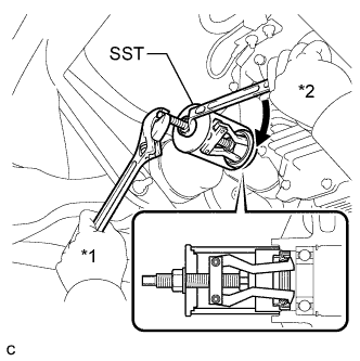
Text in Illustration *1 Hold *2 Turn RH side
-
Using SST, remove the oil seal.
- SST
- 09612-30012
-
-
-
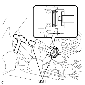
INSTALL REAR TRANSAXLE SIDE GEAR OIL SEAL
-
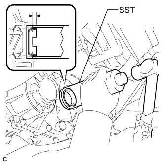
LH side
-
Using SST and a hammer, install a new oil seal.
- SST
- 09316-60011 ( 09316-00011 )
Oil seal drive in depth 7.1 to 8.1 mm (0.280 to 0.319 in.) Note
Do not damage the oil seal.
-
Apply MP grease to the oil seal lip.
-
-
RH side
-
Using SST and a hammer, install a new oil seal.
- SST
- 09350-32014 ( 09351-32150 )
- 09950-70010 ( 09951-07100 )
Oil seal drive in depth 7.1 to 8.1 mm (0.280 to 0.319 in.) Note
Do not damage the oil seal.
-
Apply MP grease to the oil seal lip.
-
-
-
INSTALL DIFFERENTIAL SIDE GEAR SHAFT SUB-ASSEMBLY
-
Install a new snap ring.
-
Text in Illustration *1 LH Side *2 RH Side Using SST, install the side gear shaft.
- SST
- 09520-24010 ( 09520-04010, 09520-32040 )
Note
-
Set the snap ring with the opening side facing downward.
-
Do not tap in the side gear shaft at an angle. If the snap ring is installed at an angle, replace it with a new one and tap in the shaft again.
-
Do not damage the oil seal.
-
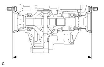
Using a vernier caliper, measure the distance between the right and left side gear shafts, as shown in the illustration.
Standard distance 272.9 mm (107.44 in.) or less
-
-
INSTALL REAR DRIVE SHAFT ASSEMBLY
-
Text in Illustration *1 Jack *2 Wooden Block Using a jack and wooden block, jack up the rear No. 2 suspension arm assembly to replicate standard vehicle height conditions.
Note
Do not jack up the rear No. 2 suspension arm assembly too high as the vehicle may fall.
-
Text in Illustration *1 Matchmark Align the matchmarks on the rear drive shaft assembly and rear axle hub and bearing assembly, and then insert the rear drive shaft assembly to the rear axle hub and bearing assembly.
-
Align the matchmarks.
-
Text in Illustration *1 Matchmark Install the rear drive shaft assembly with the 4 nuts and washers.
- Torque:
- 56 N*m { 571 kgf*cm, 41 ft.*lbf }
-
-
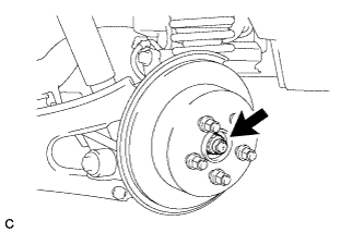
INSTALL REAR AXLE SHAFT NUT
-
Clean the threaded parts on the rear drive shaft assembly and a new rear axle shaft nut using a non-residue solvent.
Note
-
Be sure to perform this work for a new rear drive shaft assembly.
-
Keep the threaded parts free of oil and foreign matter.
-
-
Temporarily install the rear disc with the 5 hub nuts.
-
While applying the parking brakes, temporarily install the new rear axle shaft nut.
- Torque:
- 294 N*m { 2998 kgf*cm, 217 ft.*lbf }
Note
Stake the rear axle shaft nut after inspecting for looseness and runout in the following steps.
-
Remove the 5 hub nuts and the rear disc.
-
-
INSTALL REAR SUSPENSION ARM COVER (w/o Air Suspension)
-
Insert the 2 guides of the rear suspension arm cover to the rear No. 2 suspension arm assembly.
-
Install the rear suspension arm cover to the rear No. 2 suspension arm assembly with the 2 bolts as shown in the illustration.
- Torque:
- 12 N*m { 122 kgf*cm, 9 ft.*lbf }
Note
Make sure that the 2 guides of rear suspension arm cover are inserted.
-
-
INSTALL REAR SUSPENSION ARM COVER (w/ Air Suspension)
-
Insert the 2 guides of the rear suspension arm cover to the rear No. 2 suspension arm assembly.
-
Install the rear suspension arm cover to the rear No. 2 suspension arm assembly with the 2 bolts as shown in the illustration.
- Torque:
- 12 N*m { 122 kgf*cm, 9 ft.*lbf }
Note
Make sure that the 2 guides of rear suspension arm cover are inserted.
-
Check that the rear pneumatic cylinder cover is not deformed or collapsed inward.
-
-
INSTALL REAR SPEED SENSOR
-
Install the rear speed sensor to the rear axle carrier sub-assembly with the bolt.
- Torque:
- 8.0 N*m { 82 kgf*cm, 71 in.*lbf }
Note
-
Prevent foreign matter from attaching to the sensor tip.
-
Do not file the rear speed sensor installation hole or surface because the gap between the magnet rotor and rear speed sensor is important.
-
Do not twist or apply excessive force to the front speed sensor during installation to prevent it from being damaged.
-
Install the rear speed sensor without twisting it.
-
-
INSTALL TAIL EXHAUST PIPE ASSEMBLY (for RH Side)
-
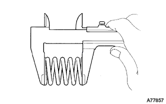
Using a vernier caliper, measure the free length of the compression springs.
Minimum length 41.5 mm (1.64 in.) If the free length is less than the minimum, replace the compression spring.
-
Fully insert a new gasket to the center exhaust pipe assembly.
-
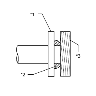
Text in Illustration *1 Center Exhaust Pipe Assembly *2 Gasket *3 Wooden Block Using a plastic hammer and wooden block, tap in the new gasket until its surface is flush with the center exhaust pipe assembly.
Note
-
Be sure to install the gasket in the correct direction.
-
Do not reuse the gasket.
-
Do not damage the gasket.
-
Do not push in the gasket by using the exhaust pipe when connecting it.
-
-
Connect the tail exhaust pipe assembly to the 2 exhaust pipe supports.
-
Install the tail exhaust pipe assembly with the 2 bolts and 2 compression springs.
- Torque:
- 43 N*m { 440 kgf*cm, 32 ft.*lbf }
-
-
INSTALL REAR WHEEL
-
ADD HYBRID TRANSAXLE FLUID
-
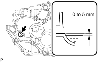
Add transaxle fluid until the transaxle fluid level is between 0 and 5 mm (0 and 0.197 in.) from the bottom lip of the transaxle filler plug opening.
Note
-
Stop the vehicle on a flat road.
-
Recheck the transaxle fluid level after driving when exchanging transaxle fluid.
-
Insufficient or excessive amounts of transaxle fluid may be the cause of some trouble.
Capacity 1.8 liters (1.9 US qts, 1.6 Imp. qts) -
-
-
INSPECT AND ADJUST HYBRID TRANSAXLE FLUID
-
Check that the transaxle fluid level is between 0 and 5 mm (0 and 0.197 in.) from the lowest position of the inner surface of the transaxle filler plug opening.
Note
-
Stop the vehicle on a flat road.
-
Recheck the transaxle fluid level after driving when exchanging transaxle fluid.
-
Insufficient or excessive amounts of transaxle fluid may be the cause of some trouble.
Capacity 1.8 liters (1.9 US qts, 1.6 Imp. qts) -
-
Check for leaks if the quantity of transaxle fluid is low.
-
Using a hexagon socket wrench 10 mm, install the filler plug and a new gasket.
- Torque:
- 39 N*m { 398 kgf*cm, 29 ft.*lbf }
-
-
INSPECT FOR EXHAUST GAS LEAK (for RH Side)
-
CHECK FOR SPEED SENSOR SIGNAL
-
Check for the speed sensor signal Click here.
-