DIFFERENTIAL SIDE GEAR SHAFT REMOVAL

Tech Tips
-
Use the same procedure for the RH side and LH side.
-
The procedure listed below is for the LH side.
-
PRECAUTION (w/ Air Suspension)
Note
Be sure to read Precaution thoroughly before servicing Click here.
-
DRAIN HYBRID TRANSAXLE FLUID
-
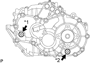
Text in Illustration *1 Filler Plug *2 Drain Plug Using a hexagon socket wrench 10 mm, remove the filler plug and gasket.
-
Using a hexagon socket wrench 10 mm, remove the drain plug and gasket.
-
Using a hexagon socket wrench 10 mm, install the drain plug and a new gasket.
- Torque:
- 39 N*m { 398 kgf*cm, 29 ft.*lbf }
-
-
REMOVE REAR WHEEL
-
REMOVE TAIL EXHAUST PIPE ASSEMBLY (for RH Side)
-
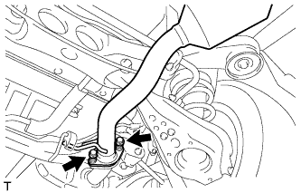
Remove the 2 bolts and 2 compression springs.
-
Remove the tail exhaust pipe assembly from the 2 exhaust pipe supports.
-
Remove the gasket from the center exhaust pipe assembly.
-
-
SEPARATE REAR SPEED SENSOR
-
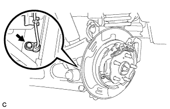
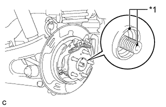
Remove the bolt and separate the rear speed sensor from the rear axle carrier sub-assembly.
Note
-
Prevent foreign matter from attaching to the rear speed sensor tip.
-
Clean the rear speed sensor installation hole and the contact surfaces every time the rear speed sensor is removed.
-
Do not twist or apply excessive force to the rear speed sensor during removal from the rear axle carrier sub-assembly to prevent it from being damaged.
-
-
-
REMOVE REAR AXLE SHAFT NUT
-
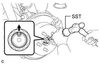
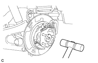
Using SST and a hammer, release the staked part of the rear axle shaft nut.
- SST
- 09930-00010
Note
Loosen the staked part of the nut completely, otherwise the threads of the rear drive shaft assembly may be damaged.
-
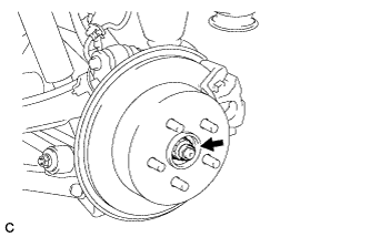
While applying the parking brakes, remove the rear axle shaft nut from the rear drive shaft assembly.
-
-
REMOVE REAR SUSPENSION ARM COVER (w/o Air Suspension)
-
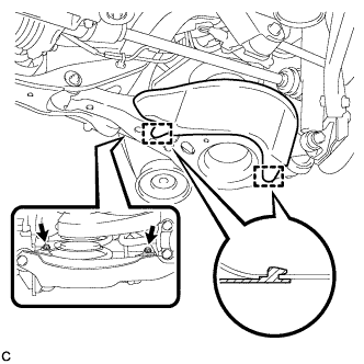
Remove the 2 bolts.
-
Disengage the 2 guides and remove the rear suspension arm cover from the rear No. 2 suspension arm assembly.
-
-
REMOVE REAR SUSPENSION ARM COVER (w/ Air Suspension)
-
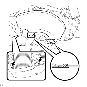
Remove the 2 bolts.
-
Disengage the 2 guides and remove the rear suspension arm cover from the rear No. 2 suspension arm assembly.
-
-
REMOVE REAR DRIVE SHAFT ASSEMBLY
-
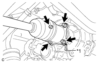
Text in Illustration *1 Matchmark Put matchmarks on the rear drive shaft assembly and differential side gear shaft.
-
Remove the 4 nuts, washers and rear drive shaft assembly.
-
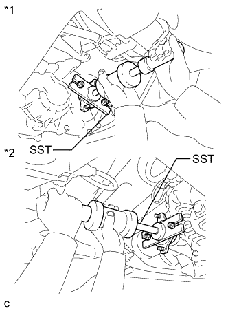
Text in Illustration *1 Jack *2 Wooden Block Using a jack and wooden block, jack up the rear No. 2 suspension arm assembly to replicate standard vehicle height conditions.
Note
Do not jack up the rear No. 2 suspension arm assembly too high as the vehicle may fall.
-
Text in Illustration *1 Matchmark Put matchmarks on the rear drive shaft assembly and rear axle hub and bearing assembly.
-
Using a plastic hammer, separate the rear drive shaft assembly from the rear axle hub and bearing assembly.
Tech Tips
If it is difficult to separate, tap the end of the rear drive shaft assembly using a brass bar and a hammer.
-
Push the rear drive shaft inboard joint assembly toward the outside of the vehicle and remove the rear drive shaft assembly LH from the differential side gear shaft sub-assembly.
-
-
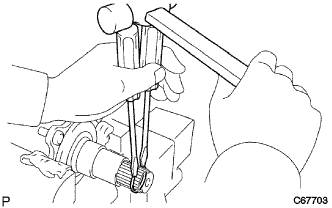
REMOVE DIFFERENTIAL SIDE GEAR SHAFT SUB-ASSEMBLY
-
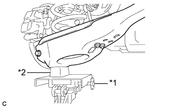
Text in Illustration *1 LH Side *2 RH Side Using SST, remove the side gear shaft.
- SST
- 09520-24010 ( 09520-04010, 09520-32040 )
Note
Do not damage the oil seal.
-
Using 2 screwdrivers and a hammer, remove the side gear shaft snap ring.
-
-
REMOVE DUST COVER
-
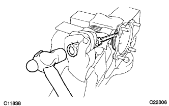
Clamp the side gear shaft in a vise.
Note
Do not damage the side gear shaft.
-
Using a screwdriver and a hammer, remove the dust cover.
-