FRONT AXLE HUB ON-VEHICLE INSPECTION

Note
When the brake pedal is first depressed after replacing the brake pads or pushing back the disc brake piston, DTC C1341, C1342, C1343 and/or C1344 may be stored. As there is no malfunction, clear the DTC(s).
Tech Tips
-
Use the same procedure for the RH side and LH side.
-
The procedure listed below is for the LH side.
-
PRECAUTION (w/ Air Suspension)
Note
Be sure to read Precaution thoroughly before servicing Click here.
-
REMOVE FRONT WHEEL
-
SEPARATE FRONT DISC BRAKE CALIPER ASSEMBLY
-
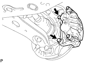
Remove the 2 bolts and separate the front disc brake caliper assembly.
Note
Use wire or an equivalent tool to keep the brake caliper from hanging down by the flexible hose.
-
-
REMOVE FRONT DISC
-
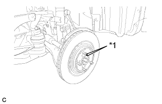
Text in Illustration *1 Matchmark Remove the front disc.
Tech Tips
Put matchmarks on the disc and the axle hub.
-
-
INSPECT FRONT AXLE HUB BEARING LOOSENESS
-
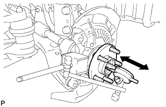
Using a dial indicator, check for looseness near the center of the front axle hub.
Maximum looseness 0 mm (0 in.) Note
-
Ensure that the dial indicator is set perpendicular to the measurement surface.
-
Keep the magnet of the dial indicator away from the front speed sensor.
Tech Tips
If the looseness exceeds the maximum, replace the front axle hub bearing.
-
-
-
INSPECT FRONT AXLE HUB RUNOUT
-
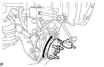
Using a dial indicator, check for runout on the surface of the axle hub outside the hub bolt.
Maximum runout 0.05 mm (0.0020 in.) Note
-
Ensure that the dial indicator is set perpendicular to the measurement surface.
-
Keep the magnet of the dial indicator away from the front speed sensor.
Tech Tips
If the runout exceeds the maximum, replace the front axle hub.
-
-
-
INSTALL FRONT DISC
-
Text in Illustration *1 Matchmark Align the matchmarks and install the front disc.
Note
When replacing the disc with a new one, select the installation position where the front disc has minimal runout.
-
-
INSTALL FRONT DISC BRAKE CALIPER ASSEMBLY
-
Install the front disc brake caliper assembly to the steering knuckle with the 2 bolts.
- Torque:
- 104 N*m { 1061 kgf*cm, 77 ft.*lbf }
-
-
INSTALL FRONT WHEEL
- Torque:
- 103 N*m { 1050 kgf*cm, 76 ft.*lbf }