HYBRID TRANSAXLE OIL SEAL REPLACEMENT

Tech Tips
-
Use the same procedure for the RH side and LH side.
-
The procedure listed below is for the LH side.
-
PRECAUTION (w/ Air Suspension)
Note
Be sure to read Precaution thoroughly before servicing Click here.
-
REMOVE FRONT WHEELS
-
DRAIN HYBRID TRANSAXLE FLUID
-
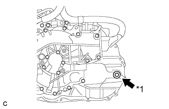
Text in Illustration *1 Filler Plug Using a hexagon socket wrench 10 mm, remove the filler plug and gasket.
-
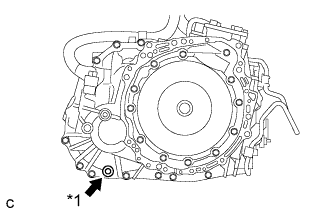
Text in Illustration *1 Drain Plug Using a hexagon socket wrench 10 mm, remove the drain plug and gasket.
-
Using a hexagon socket wrench 10 mm, install the drain plug and a new gasket.
- Torque:
- 39 N*m { 398 kgf*cm, 29 ft.*lbf }
-
-
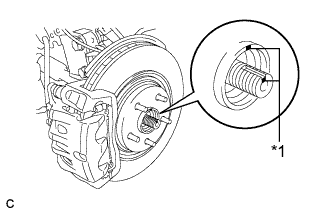
REMOVE FRONT AXLE SHAFT NUT
-
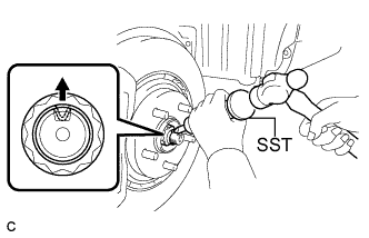
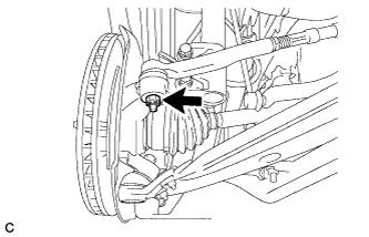
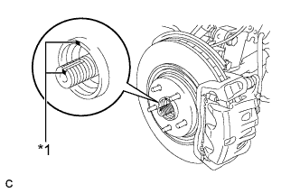
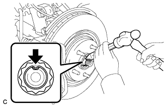
Using SST and a hammer, release the staked part of the front axle shaft nut.
- SST
- 09930-00010
Note
Loosen the staked part of the nut completely, otherwise the threads of the drive shaft may be damaged.
-
While applying the brakes, remove the front axle shaft nut.
-
-
SEPARATE FRONT STABILIZER LINK ASSEMBLY
-
Remove the nut and separate the front stabilizer link assembly from the front shock absorber.
Tech Tips
If the ball joint turns together with the nut, use a hexagon wrench (6 mm) to hold the stud bolt.
-
-
SEPARATE FRONT SPEED SENSOR
-

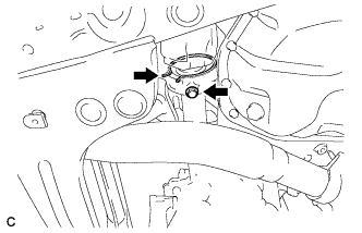
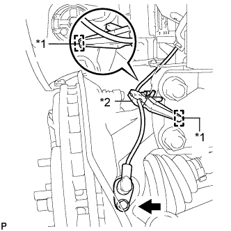
Text in Illustration *1 Hole *2 Resin Clamp Remove the bolt and resin clamp, and separate the front speed sensor.
Note
-
Be sure to completely separate the front speed sensor from the front shock absorber with coil spring.
-
Be careful not to damage the front speed sensor.
-
Clean the speed sensor installation hole and the contact surfaces every time the speed sensor is removed.
-
-
-
SEPARATE TIE ROD ASSEMBLY
-
Remove the cotter pin and nut.
-
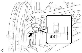
Install SST to the tie rod end.
- SST
- 09960-20010 ( 09961-02060 )
Note
Make sure that the upper ends of the tie rod end and SST are aligned.
-
Using SST, separate the tie rod end from the steering knuckle.
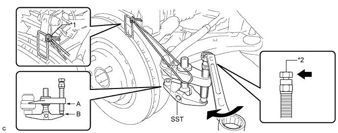
Text in Illustration *1 Tie the string without allowing for any slack. *2 Place the wrench here. - SST
- 09960-20010 ( 09961-02010 )
Note
-
When securing SST to the steering knuckle, be sure to tighten SST using a string to prevent it from falling.
-
Install SST so that A and B are parallel.
-
Be sure to place a wrench on the part indicated in the illustration.
-
Do not damage the front disc brake dust cover.
-
Do not damage the ball joint dust cover.
-
Do not damage the steering knuckle.
-
-
SEPARATE NO. 1 FRONT SUSPENSION LOWER ARM
-
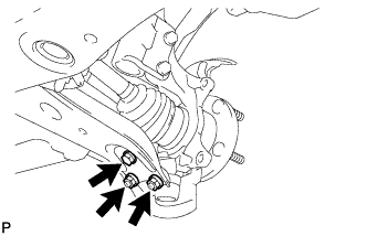
Remove the bolt and 2 nuts, and separate the front lower suspension arm from the lower ball joint.
-
-
SEPARATE FRONT DRIVE SHAFT ASSEMBLY
-
Text in Illustration *1 Matchmark Put matchmarks on the front drive shaft assembly and the front axle hub sub-assembly.
-
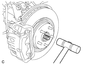
Using a plastic hammer, separate the front drive shaft assembly from the front axle assembly.
Note
Loosen the staked part of the front axle hub nut completely, otherwise the threads of the drive shaft may be damaged.
-
-
REMOVE FRONT DRIVE SHAFT ASSEMBLY LH
-
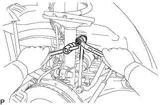
Using SST, remove the front drive shaft assembly LH.
- SST
- 09520-00031
- 09520-01010
Note
-
Be careful not to damage the drive shaft dust cover, boot or oil seal.
-
Be careful not to drop the drive shaft assembly.
-
-
REMOVE FRONT DRIVE SHAFT HOLE SNAP RING LH
-
Using a screwdriver, remove the front drive shaft hole snap ring.
-
-
REMOVE FRONT DRIVE SHAFT ASSEMBLY RH
-
Remove the bearing bracket hole snap ring from the drive shaft bearing bracket.
-
Remove the bolt and front drive shaft assembly RH from the drive shaft bearing bracket.
Note
Do not damage the boot or oil seal.
-
-
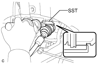
REMOVE HYBRID VEHICLE TRANSAXLE ASSEMBLY TYPE T OIL SEAL
-
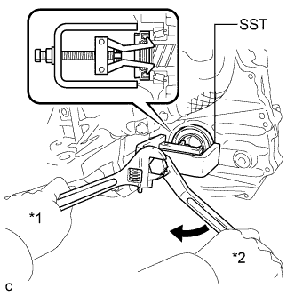
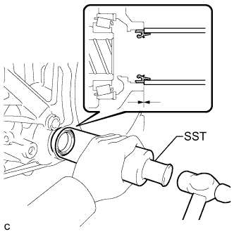
Text in Illustration *1 Hold *2 Turn Remove the LH side oil seal.
-
Using SST, remove the oil seal.
- SST
- 09514-35011
-
-
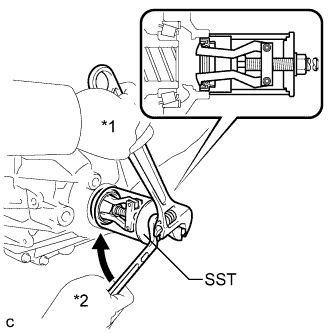
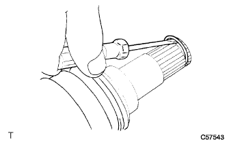
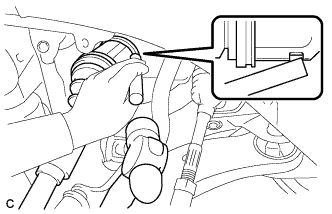
Text in Illustration *1 Hold *2 Turn Remove the RH side oil seal.
-
Using SST, remove the oil seal.
- SST
- 09612-30012
-
-
-
INSTALL HYBRID VEHICLE TRANSAXLE ASSEMBLY TYPE T OIL SEAL
-
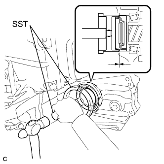
Install a new LH side oil seal.
-
Using SST and a hammer, tap in a new oil seal.
- SST
- 09223-15020
- 09950-70010 ( 09951-07100 )
Oil seal driven in depth -0.5 to 0.5 mm (-0.0197 to 0.0197 in.) -
Coat the lip of the oil seal with MP grease.
-
-
Install a new RH side oil seal.
-
Using SST and a hammer, tap in a new oil seal.
- SST
- 09316-60011 ( 09316-00011 )
Oil seal driven in depth -0.5 to 0.5 mm (-0.0197 to 0.0197 in.) -
Coat the lip of the oil seal with MP grease.
-
-
-
INSTALL FRONT DRIVE SHAFT HOLE SNAP RING LH
-
Install a new front drive shaft hole snap ring.
-
-
INSTALL FRONT DRIVE SHAFT ASSEMBLY LH
-
Align the shaft splines and install the drive shaft assembly LH with a brass bar and a hammer.
Note
-
Set the shaft snap ring with the opening facing down.
-
Be careful not to damage the drive shaft dust cover, boot or oil seal.
-
When inserting the drive shaft assembly, keep it level.
-
-

Text in Illustration *1 Matchmark Align the matchmarks and install the front drive shaft assembly LH to the front axle hub sub-assembly.
-
-
INSTALL FRONT DRIVE SHAFT ASSEMBLY RH
-
Install the front drive shaft assembly RH.
-
Install a new bearing bracket hole snap ring and the bolt.
- Torque:
- 32 N*m { 330 kgf*cm, 24 ft.*lbf }
Note
-
Do not damage the boot or oil seal.
-
When inserting the drive shaft assembly, keep it level.
-
Text in Illustration *1 Matchmark Align the matchmarks and install the front drive shaft assembly RH to the front axle hub sub-assembly.
-
-
INSTALL NO. 1 FRONT SUSPENSION LOWER ARM
-
Install the front lower suspension arm to the front lower ball joint with the bolt and 2 nuts.
- Torque:
- 92 N*m { 938 kgf*cm, 68 ft.*lbf }
-
-
INSTALL TIE ROD ASSEMBLY
-
Connect the tie rod assembly LH to the steering knuckle with the nut.
- Torque:
- 49 N*m { 500 kgf*cm, 36 ft.*lbf }
-
Install a new cotter pin.
Note
Further tighten the nut up to 60° if the holes for the cotter pin are not aligned.
-
-
INSTALL FRONT SPEED SENSOR
-
Text in Illustration *1 Hole *2 Resin Clamp Install the resin clamp and front speed sensor with the bolt.
- Torque:
- 8.0 N*m { 82 kgf*cm, 71 in.*lbf }
Note
-
Prevent foreign matter from attaching to the sensor tip.
-
Firmly insert the sensor body into the knuckle before tightening the bolt.
-
After installing the sensor to the knuckle, make sure that there is no clearance between the sensor stay and knuckle. Also make sure that no foreign matter is stuck between the parts.
-
To prevent interference between the sensor and magnetic rotor, do not rotate the sensor body during or after the insertion of the sensor body to the knuckle.
-
-
INSTALL FRONT STABILIZER LINK ASSEMBLY
-
Install the front stabilizer link assembly to the front shock absorber with the nut.
- Torque:
- 74 N*m { 755 kgf*cm, 55 ft.*lbf }
Tech Tips
If the ball joint turns together with the nut, use a hexagon wrench (6 mm) to hold the stud bolt.
-
-
INSTALL FRONT AXLE SHAFT NUT
-
Clean the threaded parts on the drive shaft and a new axle shaft nut using a non-residue solvent.
Tech Tips
-
Be sure to perform this work for a new drive shaft.
-
Keep the threaded parts free of oil and foreign objects.
-
-
Using a socket wrench (30 mm), install the axle shaft nut.
- Torque:
- 294 N*m { 2998 kgf*cm, 217 ft.*lbf }
-
Using a chisel and hammer, stake the front axle shaft nut.
-
-
INSTALL FRONT WHEELS
-
ADD HYBRID TRANSAXLE FLUID
-
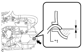
Text in Illustration *1 Filler Nozzle Add transaxle fluid until the transaxle fluid level is between 0 mm (0 in.) from the bottom lip of the filler plug opening.
Note
-
Keep the oil temperature at 5°C (41°F) or higher.
-
Stop the vehicle on a flat road.
-
Recheck the transaxle fluid level after driving following transaxle fluid replacement.
-
Insufficient or excessive amounts of transaxle fluid may be the cause of some trouble.
-
Be sure to add fluid slowly. If fluid is added quickly, the fluid may hit internal parts and bounce back, resulting in fluid coming out of the filler plug opening.
-
Be sure to fully insert the filler nozzle into the filler plug opening.
-
-
Using a hexagon socket wrench 10 mm, temporarily tighten the filler plug and gasket.
-
-
INSPECT AND ADJUST HYBRID TRANSAXLE FLUID
-
Set the vehicle to FWD inspection mode Click here.
-
After waiting for 1 minute or more, stop the engine.
-
Text in Illustration *1 Filler Plug Using a hexagon socket wrench 10 mm, remove the filler plug and gasket.
-
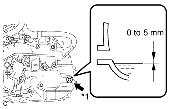
Add transaxle fluid until the transaxle fluid level is between 0 and 5 mm (0 and 0.197 in.) from the bottom lip of the filler plug opening.
Note
-
Keep the transaxle fluid temperature at 5°C (41°F) or higher.
-
Stop the vehicle on a flat road.
-
Recheck the transaxle fluid level after driving following transaxle fluid replacement.
-
Insufficient or excessive amounts of transaxle fluid may be the cause of some trouble.
-
Be sure to add fluid slowly. If fluid is added quickly, the fluid may hit internal parts and bounce back, resulting in fluid coming out of the filler plug opening.
-
Be sure to directly check that the transaxle fluid level is within the specified range.
-
-
After adding fluid, leave it for 30 seconds so that the fluid surface can become still again, and then check that the fluid level is between 0 to 5 mm (0 to 0.197 in.) from the bottom lip of the filler plug opening. (If the fluid is insufficient, return to the Add Hybrid Transaxle Fluid procedure.)
-
Check for leaks if the quantity of transaxle fluid is low.
-
Using a hexagon socket wrench 10 mm, install the filler plug and a new gasket.
- Torque:
- 39 N*m { 398 kgf*cm, 29 ft.*lbf }
-
-
INSPECT AND ADJUST FRONT WHEEL ALIGNMENT
-
Inspect and adjust the front wheel alignment Click here.
-
-
CHECK ABS SPEED SENSOR SIGNAL
-
Check for the speed sensor signals Click here.
-