TRANSMISSION CONTROL CABLE INSTALLATION

-
INSTALL TRANSMISSION CONTROL CABLE ASSEMBLY
Note
When connecting the transmission control cable, install the shift lever first and then the control shaft lever side.
-
Pass the control cable from the cabin to the engine compartment.
-
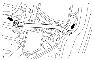
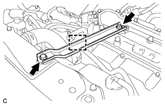
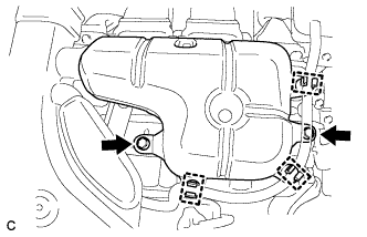
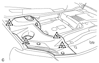
Install the transmission control cable assembly with the 3 bolts.
- Torque:
- 5.0 N*m { 51 kgf*cm, 44 in.*lbf }
-
Connect the transmission control cable assembly to the 3 transmission control cable brackets.
-
-
INSTALL INVERTER WITH CONVERTER ASSEMBLY
CAUTION:
Wear insulating gloves.
-
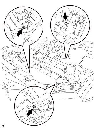
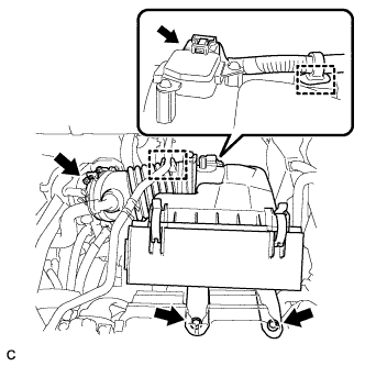
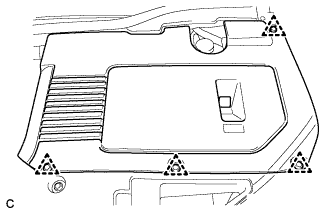
Install the inverter with converter assembly with the 2 bolts and nut.
- Torque:
- 21 N*m { 214 kgf*cm, 15 ft.*lbf }
Note
-
Since the inverter with converter assembly is very heavy, 2 people are needed to remove the inverter with converter assembly. When removing the inverter with converter assembly, do not damage the parts around it.
-
To prevent damage, do not hold the inverter with converter assembly by the connectors.
-
To prevent damage due to static electricity, do not touch the terminals of the disconnected connectors.
-
-
INSTALL CONDENSER
-

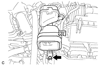
Install the condenser with the bolt.
- Torque:
- 8.4 N*m { 86 kgf*cm, 74 in.*lbf }
-
-
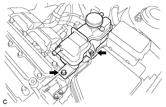
INSTALL RADIATOR RESERVE TANK ASSEMBLY
-
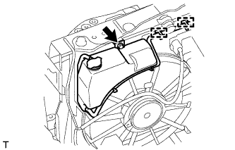
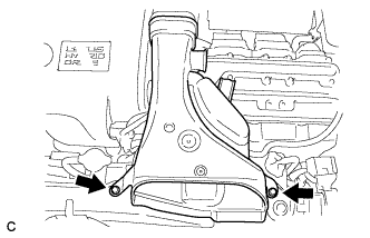
Install the radiator reserve tank with the bolt and connect the 2 clamps to the radiator.
- Torque:
- 5.3 N*m { 54 kgf*cm, 47 in.*lbf }
-
-
INSTALL NO. 4 INVERTER BRACKET
-
Install the No. 4 inverter bracket with the bolt and nut.
- Torque:
- 21 N*m { 214 kgf*cm, 15 ft.*lbf }
-
-
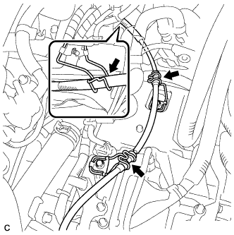
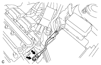
CONNECT NO. 2 ENGINE ROOM WIRE
-
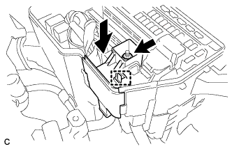
Engage the claw and connect the No. 2 engine room wire with the nut.
- Torque:
- 8.4 N*m { 86 kgf*cm, 74 in.*lbf }
-
Connect the clamp.
-
Install the relay block cover.
-
-
CONNECT WATER HOSE
-
Text in Illustration *1 Match Mark Connect the 2 water hoses with the hose clamp to the inverter with converter assembly.
Note
-
Align the match marks of the hoses and pipes.
-
Be sure to insert the hose until it reaches the rib on the pipe.
-
Align the hose clamps to the markings as shown in the illustration.
Tech Tips
Each direction of the hose and hose clamp is indicated in the illustration.
-
-
Text in Illustration *1 Retainer Connect the water hose to the inverter with converter assembly and lock the hose with the retainer.
Note
-
Insert the retainer until a click sound is heard.
-
Pull on the hose to confirm that the hose is securely connected.
-
-
-
CONNECT MG ECU CONNECTOR
Note
-
Make sure that the connectors are fully engaged.
-
Do not allow any foreign objects or water to enter the inverter with converter assembly.
-
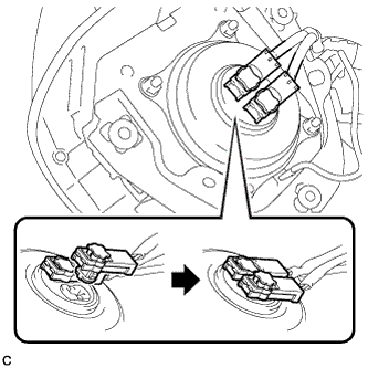
Connect the connector to the inverter with converter assembly.
-
Connect the low voltage connector to the inverter with converter assembly and lock the connector with the lock lever.
-
-
INSTALL RELAY BLOCK SUB-ASSEMBLY
-
Install the relay block sub-assembly with the clamp.
-
-
INSTALL NO. 6 INVERTER BRACKET (w/ Bracket)
-
Install the No. 6 inverter bracket with the 2 bolts.
- Torque:
- 21 N*m { 214 kgf*cm, 15 ft.*lbf }
-
-
REMOVE INVERTER TERMINAL COVER
-
Remove the 11 bolts and inverter cover from the inverter with converter assembly.
Note
Make sure to pull the inverter cover straight up, as a connector is connected to the bottom of the cover.
-
-
CONNECT NO. 3 WIRE FRAME
CAUTION:
Wear insulating gloves.
Note
-
Make sure that the interlock are fully engaged.
-
Do not allow any foreign objects or water to enter the inverter with converter assembly.
-
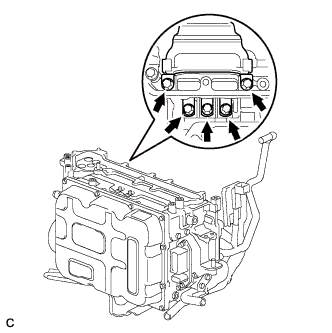
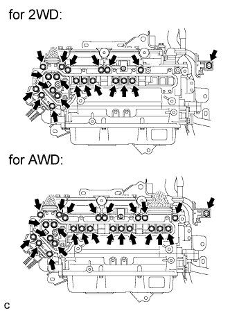
Connect the No. 3 wire frame (high voltage cables of the hybrid battery) with the 4 bolts to the inverter with converter assembly.
- Torque:
- 8.0 N*m { 82 kgf*cm, 71 in.*lbf }
Note
Be sure to use a torque wrench to tighten the bolt.
-
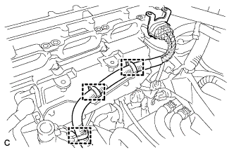
Connect the 3 clamps.
-
-
CONNECT HIGH VOLTAGE CABLE OF FRONT MOTOR
CAUTION:
Wear insulating gloves.
Note
Do not allow any foreign objects or water to enter the inverter with converter assembly.
-
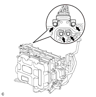
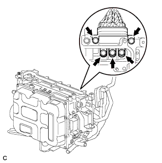
Connect the high voltage cable of the generator (MG1) with the 5 bolts to the inverter with converter assembly.
- Torque:
- 8.0 N*m { 82 kgf*cm, 71 in.*lbf }
-
Connect the high voltage cable of the motor (MG2) with 5 bolts to the inverter with converter assembly.
- Torque:
- 8.0 N*m { 82 kgf*cm, 71 in.*lbf }
-
-
CONNECT NO. 3 WIRE FRAME (for AWD)
CAUTION:
Wear insulating gloves.
Note
Do not allow any foreign objects or water to enter the inverter with converter assembly.
-
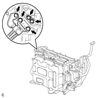
Connect the No. 3 wire frame (high voltage cable of the rear motor (MGR)) with 5 bolts to the inverter with converter assembly
- Torque:
- 8.0 N*m { 82 kgf*cm, 71 in.*lbf }
-
Connect the clamp.
-
-
CONNECT NO. 4 ENGINE WIRE
CAUTION:
Wear insulating gloves.
Note
Do not allow any foreign objects or water to enter the inverter with converter assembly.
-
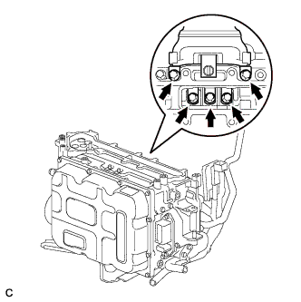
Connect the No. 4 engine wire (high voltage cables of the air conditioning) with the 5 bolts to the inverter with converter assembly
- Torque:
- 8.0 N*m { 82 kgf*cm, 71 in.*lbf }
-
-
CHECK HIGH VOLTAGE CABLE CONNECTION
CAUTION:
Wear insulating gloves.
Note
Do not allow any foreign objects or water to enter the inverter with converter assembly.
-
Check that each connector and terminal is firmly installed.
- Torque:
- for Bolt
- 8.0 N*m { 82 kgf*cm, 71 in.*lbf }
- for Nut
- 8.4 N*m { 86 kgf*cm, 74 in.*lbf }
Note
Make sure that the bolts are fully tightened.
-
-
INSTALL INVERTER TERMINAL COVER
CAUTION:
Wear insulating gloves.
Note
-
Make sure that the interlock are fully engaged.
-
Do not allow any foreign objects or water to enter the inverter with converter assembly.
-
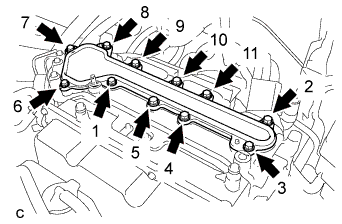
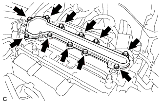
Using several steps, install the inverter terminal cover with the 11 bolts uniformly in the sequence shown in the illustration.
- Torque:
- 8.0 N*m { 82 kgf*cm, 71 in.*lbf }
-
-
INSTALL NO. 1 INVERTER RESERVE TANK BRACKET
-
Install the No. 1 inverter reserve tank bracket with the 2 bolts to the inverter with converter assembly.
- Torque:
- 10 N*m { 102 kgf*cm, 7 ft.*lbf }
-
-
INSTALL INVERTER RESERVE TANK ASSEMBLY
-
Install the inverter reserve tank with the bolt and nut to the No. 1 inverter reserve tank bracket.
- Torque:
- 10 N*m { 102 kgf*cm, 7 ft.*lbf }
-

Connect the 3 water hoses to the inverter reserve tank sub-assembly with the 3 hose clamps.
-
Connect the hose to the clamp.
-
-
INSTALL NO. 3 INVERTER BRACKET
-
Install the No. 3 inverter bracket with the 2 bolts.
- Torque:
- 10 N*m { 102 kgf*cm, 7 ft.*lbf }
-
Install the hose clamp to the No. 3 inverter bracket.
-
-
INSTALL AIR CLEANER ASSEMBLY WITH HOSE
-
Install the air cleaner assembly with hose with the 2 bolts.
- Torque:
- 5.5 N*m { 56 kgf*cm, 49 in.*lbf }
-
Install the air cleaner hose with the band.
-
Install the No. 1 fuel vapor feed hose to the air cleaner hose.
-
Connect the air flow meter connector and harness clamp.
-
-
INSTALL INLET NO. 1 AIR CLEANER
-
Install the inlet No. 1 air cleaner with the bolt.
- Torque:
- 8.0 N*m { 82 kgf*cm, 71 in.*lbf }
-
Connect the No. 1 fuel vapor feed hose to the clamp.
-
-
INSTALL INLET NO. 2 AIR CLEANER
-
Install the inlet No. 2 air cleaner with the 2 bolts.
- Torque:
- 8.0 N*m { 82 kgf*cm, 71 in.*lbf }
-
-
INSTALL INTAKE AIR RESONATOR SUB-ASSEMBLY
-
Install the intake air resonator sub-assembly with the 2 bolts.
- Torque:
- 8.0 N*m { 82 kgf*cm, 71 in.*lbf }
-
Connect the 3 water hose clamps to the intake air resonator sub-assembly.
-
-
INSTALL INSTRUMENT PANEL REINFORCEMENT ASSEMBLY WITH AIR CONDITIONING UNIT ASSEMBLY
Tech Tips
Refer to the procedure from Install Instrument Panel Reinforcement Assembly with Air Conditioning Unit Assembly Click here.
-
CONNECT TRANSMISSION CONTROL CABLE ASSEMBLY
Note
Before installing the transmission control cable assembly, check that the shift lever position sensor and the shift lever are in neutral.
-
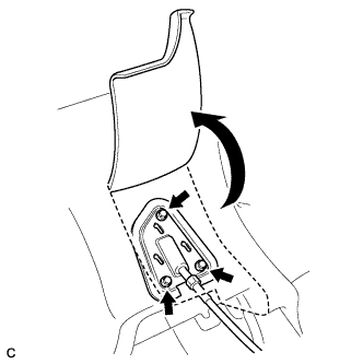
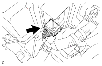
Turn back the boot.
-
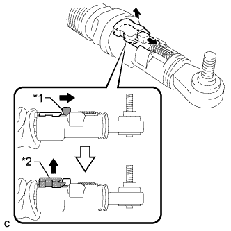
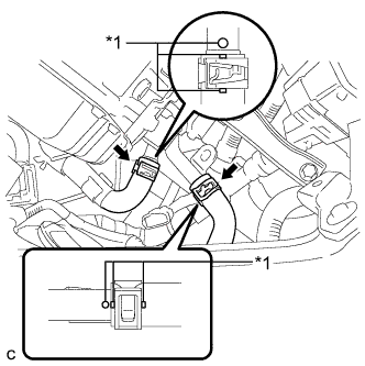
Text in Illustration *1 Slider *2 Lock Piece Slide the slider of the transmission control cable in the direction indicated by the arrow and pull the lock piece outward.
-
Install a new clip to the control cable bracket.
-
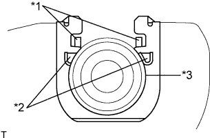
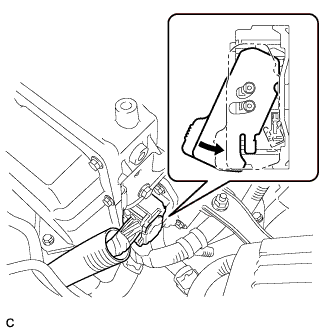
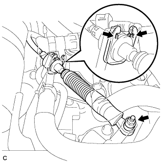
Text in Illustration *1 Claw A *2 Claw B *3 Control Cable Install the control cable to the control cable bracket.
Note
-
Make sure that the claws A on the clip are securely fit into the bracket holes.
-
Make sure that the cable is securely installed inside of the claws B of the clip.
-
-
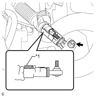
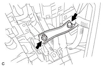
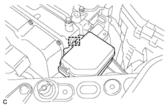
Text in Illustration *1 Lock Piece Connect the transmission control cable to the control shaft lever with the nut.
- Torque:
- 12 N*m { 122 kgf*cm, 9 ft.*lbf }
Note
Check that the lock piece is pulled up.
-
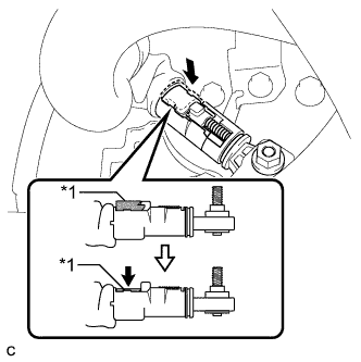
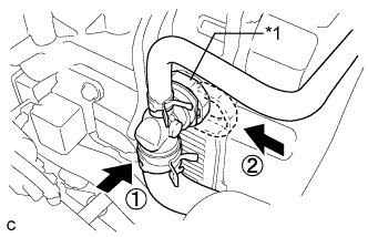
Text in Illustration *1 Lock Piece Push the lock piece into the adjuster case.
Note
-
Check that the shift lever position sensor and the shift lever are in neutral.
-
Securely push in the lock piece until the slider lock is engaged.
-
-
Refit the boot.
-
-
CONNECT CABLE TO NEGATIVE BATTERY TERMINAL
Note
When disconnecting the cable, some systems need to be initialized after the cable is reconnected Click here.
-
INSTALL REAR DECK FLOOR BOX
-

Install the rear deck floor box with the 3 clips.
-
-
INSTALL SERVICE PLUG GRIP
CAUTION:
Wear insulated gloves.
Note
Before connecting the service plug, check that no parts and tools remain and that the high voltage terminals and connectors are connected securely.
-
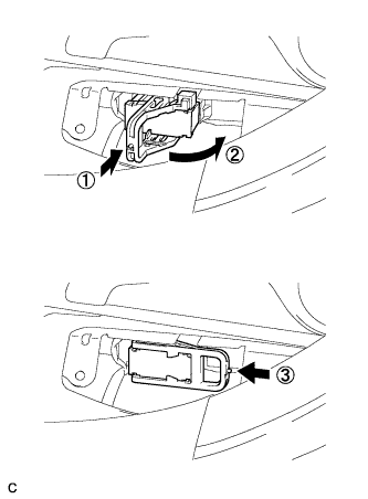
Wear insulated gloves and insert the service plug grip in the order shown in the illustration.
-
Tilt the service plug grip 90° and slide it down until a click sound is heard.
-
-
INSTALL BATTERY SERVICE HOLE COVER
-
Engage the 2 clips, 2 guides and install the battery service hole cover.
Note
Make sure that the battery service hole cover is installed securely.
-
-
ADD COOLANT (for Inverter)
Note
-
Do not reuse the drained coolant because it may contain foreign objects.
-
If the vehicle is driven with air in the inverter cooling system, the following DTCs may be set.
DTC Code Detection Item P0A01-726 Motor Electronics Coolant Temperature Sensor Circuit Range / Performance P0A04-725 Motor Electronics Coolant Temperature Sensor Circuit Intermittent P0A08-264 DC / DC Converter Status Circuit P0A78-284 Drive Motor "A" Inverter Performance P0A78-286 Drive Motor "A" Inverter Performance P0A79-692 Drive Motor "B" Inverter Performance P0A79-696 Drive Motor "B" Inverter Performance P0A7A-322 Generator Inverter Performance P0A7A-324 Generator Inverter Performance P0A93-346 Inverter Cooling System Performance P0A94-553 DC / DC Converter Performance P0A94-557 DC / DC Converter Performance P0AEE-277 Motor Inverter Temperature Sensor "A" Circuit Range / Performance P0AF1-276 Drive Motor Inverter Temperature Sensor "A" Circuit Intermittent / Erratic P0AF3-676 Sensor of Rear Motor Inverter Temperature P0AF6-675 Drive Motor Inverter Temperature Sensor "B" Circuit Intermittent / Erratic P0BCD-315 Generator Inverter Temperature Sensor Circuit Range / Performance P0BD0-314 Generator Inverter Temperature Sensor Circuit Intermittent / Erratic P0C39-626 DC / DC Converter Temperature Sensor "A" Range / Performance P0C3C-625 DC / DC Converter Temperature Sensor "A" Intermittent / Erratic P0C3E-628 DC / DC Converter Temperature Sensor "B" Range / Performance P0C41-627 DC / DC Converter Temperature Sensor "B" Intermittent / Erratic P0C73-776 Motor Electronics Coolant Pump "A" Control Performance
-
Add coolant to the reserve tank.
-
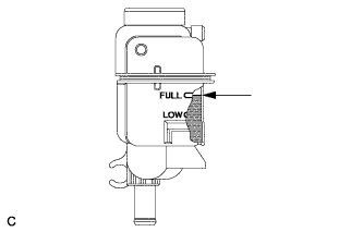
Slowly pour coolant into the radiator reservoir tank until it reaches the FULL line.
Coolant quantity 1.9 liter (2.0 US qts, 1.7 Imp. qts.) -
When using the intelligent tester:
-
Connect the intelligent tester to the DLC3.
-
Turn the power switch on (IG).
-
On the intelligent tester, enter the following menus: Powertrain / Hybrid Control / Active Test / Activate the Water Pump.
-
Keep the coolant at the FULL level in the reserve tank to compensate for the drop in coolant level when the air bleeds.
Standard Air bleeding from the coolant system is completed when the noise made by the water pump becomes smaller and the circulation of coolant in the reserve tank improves. Tech Tips
Loud noise made by the water pump and poor circulation of coolant in the reserve tank indicates that there is air in the coolant system.
-
-
When not using the intelligent tester:
-
Turn the power switch on (READY). [*1]
-
Turn the power switch off and keep the coolant at the FULL level in the reserve tank to compensate for the drop in coolant level when the air bleeds. [*2]
Note
-
Be sure to turn the power switch off before adding SLLC.
-
Do not work on the components in the engine compartment while the vehicle is in the READY-on state because the engine is in intermittent operation.
-
-
Repeat steps [*1] and [*2] until air bleeding from the coolant system is completed.
Standard Air bleeding from the coolant system is completed when the noise made by the water pump becomes smaller and the circulation of coolant in the reserve tank improves. Tech Tips
Loud noise made by the water pump and poor circulation of coolant in the reserve tank indicates that there is air in the coolant system.
-
-
Add coolant to the FULL mark of the reserve tank.
-
-
ADD COOLANT (for Engine)
-
Tighten the radiator drain cock plug by hand.
-
Tighten the 2 cylinder block drain cock plugs.
- Torque:
- 13 N*m { 130 kgf*cm, 9 ft.*lbf }
-
Loosen the air drain cock plug on the water inlet housing.
-
Add TOYOTA Super Long Life Coolant (SLLC) to the radiator inlet opening until coolant overflows from the air drain cock hole. Then tighten the air drain cock plug to the water inlet housing.
- Torque:
- 13 N*m { 130 kgf*cm, 9 ft.*lbf }
-
Slowly fill the radiator with TOYOTA Super Long Life Coolant (SLLC).
Standard Capacity Item Capacity Engine coolant 11.7 liters (12.4 US qts, 10.2 lmp. qts) Tech Tips
-
TOYOTA vehicles are filled with TOYOTA SLLC at the factory. In order to avoid damage to the engine cooling system and other technical problems, only use TOYOTA SLLC or similar high quality ethylene glycol based non-silicate, non-amine, non-nitrite, non-borate coolant with long-life hybrid organic acid technology (coolant with long-life hybrid organic acid technology is a combination of low phosphates and organic acids).
-
Contact your TOYOTA dealer for further details.
Note
Never use water as a substitute for engine coolant.
-
-
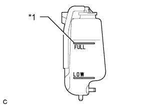
Text in Illustration *1 Full Line Slowly pour coolant into the radiator reservoir tank until it reaches the full line.
-
Install the radiator cap.
-
Squeeze the No. 1 and No. 2 radiator hoses several times by hand, and then check the level of the coolant.
If the coolant level is low, add coolant.
-
Bleed air from the cooling system.
-
Put the engine in inspection mode Click here.
-
Warm up the engine until the thermostat opens. While the thermostat is open, circulate the coolant for several minutes.
Tech Tips
The thermostat open timing can be confirmed by squeezing the No. 2 radiator hose by hand, and checking when the engine coolant starts to flow inside the hose.
-
Maintain the engine speed at 2500 rpm.
-
Squeeze the inlet and No. 1 and No. 2 radiator hoses several times by hand to bleed air.
CAUTION:
When squeezing the radiator hoses:
-
Wear protective gloves.
-
Be careful as the radiator hoses are hot.
-
Keep your hands away from the cooling fans.
Note
-
Make sure that the radiator reservoir still has some coolant in it.
-
If the coolant temperature gauge indicates an excessive temperature, turn off the engine and let it cool.
-
If there is not enough coolant, the engine may overheat or be seriously damaged.
-
If the radiator reservoir does not have enough coolant, perform the following: 1) stop the engine, 2) wait until the coolant has cooled down, and 3) add coolant until the reservoir is filled to the Full line.
-
-
-
Stop the engine and wait until the engine coolant cools down.
-
Add engine coolant to the full line on the radiator reservoir.
-
-
CHARGE WITH REFRIGERANT
-
Perform vacuum purging using a vacuum pump.
-
Charge with refrigerant HFC-134a (R134a).
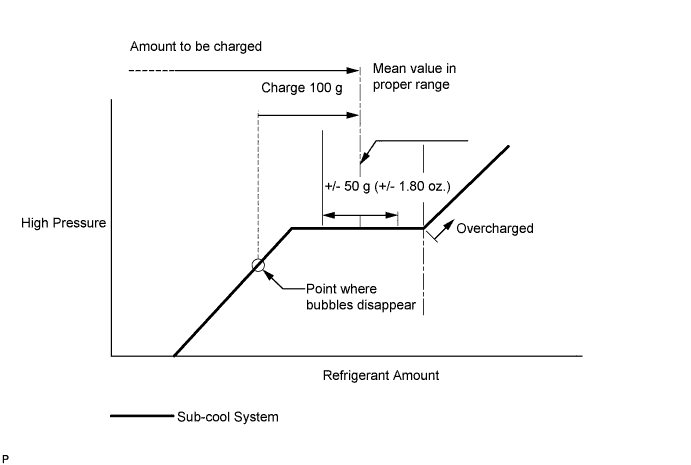
Standard 550 to 650 g (19.4 to 22.9 oz.) - SST
- 09985-20010 ( 09985-02010, 09985-02050, 09985-02060, 09985-02070, 09985-02080, 09985-02090, 09985-02110, 09985-02130, 09985-02140, 09985-02150 )
Note
-
Do not turn the A/C on before charging with refrigerant. Doing so will cause the compressor to work without refrigerant, resulting in overheating of the cooler compressor.
-
Approximately 100 g (3.53 oz.) of refrigerant may need to be charged after bubbles disappear. The refrigerant amount should be checked by quantity, not with the sight glass.
-
Avoid using the gauge manifold set that had been used for vehicles with conventional compressor oil (ND-OIL 8 or equivalent) as much as possible. This will cause compressor oil remaining in the manifold to enter the vehicle, resulting in insulation performance deterioration. A gauge manifold set that had been used 3 times or less can be reused if an appropriate one is not available.
Tech Tips
Ensure that sufficient refrigerant is available to recharge the system when using a refrigerant recovery unit. Refrigerant recovery units are not always able to recover 100% of the refrigerant from an A/C system.
-
-
WARM UP ENGINE
-
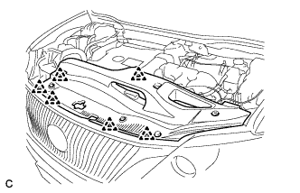
INSPECT FOR REFRIGERANT LEAK
-
After recharging with refrigerant, inspect for refrigerant leaks using a halogen leak detector.
-
Carry out the test under the following conditions:
-
Turn the power switch off.
-
Secure good ventilation (the halogen leak detector may react to volatile gases which are not refrigerant, such as evaporated gasoline and exhaust gas).
-
Repeat the test 2 or 3 times.
-
Make sure that there is some refrigerant remaining in the refrigeration system.
When the compressor is off: approx. 392 to 588 kPa (4 to 6 kgf/cm2, 57 to 85 psi)
-
-
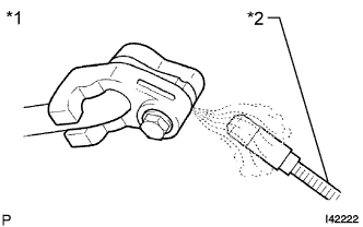
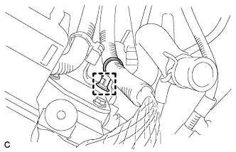
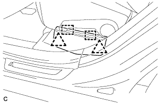
Text in Illustration *1 Inspect for Leak *2 Halogen Leak Detector Using a halogen leak detector, inspect for refrigerant leaks from the refrigerant lines.
-
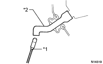
Text in Illustration *1 Halogen Leak Detector *2 Drain Hose Bring the halogen leak detector close to the drain hose with the detector's power off, and then turn the detector on.
Tech Tips
-
After the blower motor has stopped, let the cooling unit stand for more than 15 minutes.
-
Bring the halogen leak detector sensor under the drain hose.
-
When bringing the halogen leak detector close to the drain hose, make sure that the halogen leak detector does not react to volatile gases. If it is not possible to avoid interference from volatile gases, the vehicle should be lifted up to allow testing.
-
-
If a refrigerant leak is not detected from the drain hose, remove the blower motor control from the cooling unit. Insert the halogen leak detector sensor into the unit and perform the test.
-
Disconnect the pressure switch connector and leave it for approximately 20 minutes. Bring the halogen leak detector close to the pressure switch and perform the test.
-
-
INSPECT FOR COOLANT LEAK (for Inverter)
-
Remove the reserve tank cap.
CAUTION:
To avoid the danger of being burned, do not remove the reserve tank cap while the coolant for the inverter is still hot.
-
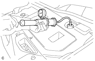
Install the radiator cap tester.
-
Pump the radiator cap tester to 118 kPa (1.2 kgf/ cm2, 17 psi), and then check that the pressure does not drop.
Tech Tips
If the pressure drops, check the hoses, radiator, water pump, inverter with converter, and hybrid vehicle transaxle assembly for leaks.
-
Reinstall the reserve tank cap.
-
-
INSPECT FOR COOLANT LEAK (for Engine)
CAUTION:
Do not remove the radiator cap while the engine and radiator are still hot. Pressurized hot engine coolant and steam may be released and cause serious burns.
Note
Before performing each inspection, turn the A/C switch off.
-
Remove the radiator cap.
-
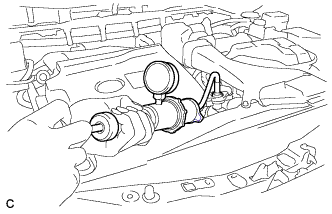
Fill the radiator with coolant and attach a radiator cap tester.
-
Put the engine in inspection mode Click here.
-
Warm up the engine.
-
Using the radiator cap tester, increase the pressure inside the radiator to 118 kPa (1.2 kgf/cm2, 17 psi), and check that the pressure does not drop.
If the pressure drops, check the hoses, radiator, exhaust center pipe assembly and the heater hose around the water temperature switch and engine water pump for leaks. If no external leaks are found, check the heater core, cylinder block and cylinder head.
-
Remove the radiator cap tester.
-
Install the radiator cap.
-
-
INSTALL V-BANK COVER SUB-ASSEMBLY
-
Fit the 4 retainers and install the V-bank cover sub-assembly.
-
-
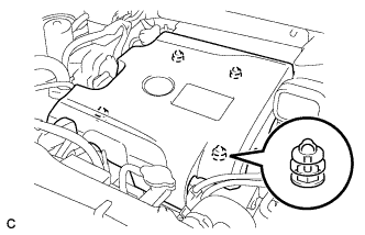
INSTALL COOL AIR INTAKE DUCT SEAL
-
Install the cool air intake duct seal with the 6 clips.
-
-
INSTALL ENGINE ROOM SIDE COVER
-
Install the engine room side cover with the 4 clips.
-
-
INSTALL ENGINE ROOM SIDE COVER LH
-
Install the engine room side cover with the 4 clips.
-
-
PLACE FRONT WHEELS FACING STRAIGHT AHEAD
-
INSPECT STEERING PAD
-
Check that the power switch is off.
-
Check that the cable is disconnected from the negative (-) battery terminal.
CAUTION:
Wait at least 90 seconds after disconnecting the cable from the negative (-) battery terminal to disable the SRS system.
-
Connect the airbag connectors to the steering pad.
Note
-
When connecting any airbag connector, take care not to damage the airbag wire harness.
-
Be sure to only connect the connectors to each corresponding color.
-
-
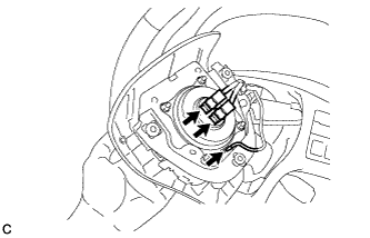
Push in the lock to install the airbag connector.
-
Connect the horn connector to the steering pad.
-
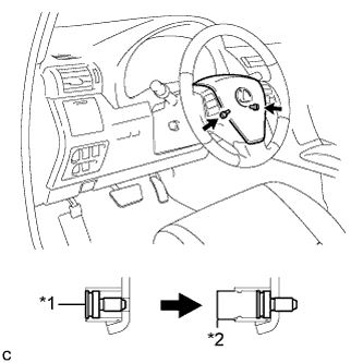
Text in Illustration *1 "TORX" Screw *2 Screw Case Confirm that the circumference groove of each "TORX" screw fits in the screw case, and place the steering pad onto the steering wheel assembly.
-
Using a T30 "TORX" socket wrench, tighten the 2 "TORX" screws.
- Torque:
- 8.8 N*m { 90 kgf*cm, 78 in.*lbf }
-
-
INSPECT SUSPENSION CONTROL SYSTEM (w/ Air Suspension)
-
Inspect the suspension control system Click here.
-
-
INSPECT SRS WARNING LIGHT
-
Inspect the SRS warning light Click here.
-
-
INSPECT SHIFT LEVER POSITION
-
When moving the shift lever from P to R with the power switch on (IG) and the brake pedal depressed, make sure that the shift lever moves smoothly and correctly into position.
-
Turn the power switch on (READY) and make sure that the vehicle moves forward when moving the shift lever from N to D and moves rearward when moving the shift lever to R.
If the operation cannot be performed as specified, inspect the shift lever position sensor and check the shift lever assembly installation condition.
-
-
ADJUST SHIFT LEVER POSITION
-
Apply the parking brake and move the shift lever to N.
Note
Check that the control shaft lever and the shift lever are in neutral.
-
Remove the No. 1 engine under cover.
-
Remove the nut from the control shaft lever.
-
Using a screwdriver, disengage the 4 claws and disconnect the control cable with clip from the control cable bracket.
-
Remove the clip.
-
Turn back the boot.
-
Text in Illustration *1 Slider *2 Lock Piece Slide the slider of the transmission control cable in the direction indicated by the arrow and pull the lock piece outward.
-
Install a new clip to the control cable bracket.
-
Text in Illustration *1 Claw A *2 Claw B *3 Control Cable Install the control cable to the control cable bracket.
Note
-
Make sure that the claws A on the clip are securely fit into the bracket holes.
-
Make sure that the cable is securely installed inside of the claws B of the clip.
-
-
Text in Illustration *1 Lock Piece Connect the transmission control cable to the control shaft lever with the nut.
- Torque:
- 12 N*m { 122 kgf*cm, 9 ft.*lbf }
Note
Check that the lock piece is pulled up.
-
Text in Illustration *1 Lock Piece Push the lock piece into the adjuster case.
Note
-
Check that the shift lever position sensor and the shift lever are in neutral.
-
Securely push in the lock piece until the slider lock is engaged.
-
-
Refit the boot.
-
After adjusting the shift lever position, check the operation and function of the shift lever. If there is a problem, adjust the position again.
-
Install the No. 1 engine under cover.
-
-
INSPECT SHIFT LEVER OPERATION
-
While moving the shift lever from N to each position, check that the lever moves smoothly and that the shift position indicator comes on properly according to the shift lever position.
-
Turn the power switch on (READY) and check the following:
-
When the shift lever is moved to D, the vehicle moves forward.
-
When the shift lever is moved to R, the vehicle moves in reverse.
Note
The vehicle should not move when the shift position indicator is off.
-
-
-
INSTALL NO. 1 ENGINE UNDER COVER