CRUISE CONTROL SYSTEM Cruise Main Indicator Light Circuit
DESCRIPTION
-
The power management control ECU detects a cruise control switch signal and sends it to the combination meter assembly through CAN. Then the cruise main indicator light comes on.
-
The cruise main indicator light circuit uses CAN for communication. If there is a malfunction in this circuit, check for DTCs in the CAN communication system before troubleshooting this circuit.
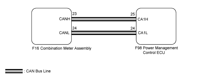
WIRING DIAGRAM
INSPECTION PROCEDURE
PROCEDURE
-
PERFORM ACTIVE TEST USING INTELLIGENT TESTER
-
Connect the intelligent tester to the DLC3.
-
Turn the power switch on (IG).
-
Turn the tester on.
-
Enter the following menus: Body Electrical / Combination Meter / Active Test.
-
Check the cruise main indicator light by performing the Active Test.
Combination Meter Tester Display Test Part Control Range Diagnostic Note Indicat. Lamp Cruise Cruise main indicator light ON / OFF - OK The display changes as shown above according to Active Test.
NG 
REPLACE COMBINATION METER ASSEMBLY Click here
OK 
-
-
READ VALUE USING INTELLIGENT TESTER
-
Connect the intelligent tester to the DLC3.
-
Turn the power switch on (IG).
-
Turn the tester on.
-
Enter the following menus: Powertrain / Cruise Control / Data List.
-
Check the Data List for proper functioning of the cruise main indicator light.
Cruise Control (Power Management Control ECU) Tester Display Measurement Item/Range Normal Condition Diagnostic Note CCS Indicator M-CPU Cruise main indicator (M-CPU)/ON or OFF ON: Cruise main indicator light on
OFF: Cruise main indicator light off
- OK The display changes as shown above according to cruise control main switch operation. Result Result Proceed to OK A NG (for LHD) B NG (for RHD) C
B
REPLACE POWER MANAGEMENT CONTROL ECU (for LHD) Click here
C
REPLACE POWER MANAGEMENT CONTROL ECU (for RHD) Click here
A 
PROCEED TO NEXT SUSPECTED AREA SHOWN IN PROBLEM SYMPTOMS TABLE Click here
-