RADIATOR REMOVAL

-
PRECAUTION (w/ Air Suspension)
CAUTION:
Be sure to read Precaution thoroughly before service Click here.
-
PRECAUTION (w/ Navigation System)
Note
After the power switch is turned off, the display and navigation module display (HDD navigation system) records various types of memory and settings. As a result, after turning the power switch off, make sure to wait for the time specified in the following table before disconnecting the cable from the negative (-) battery terminal.
Waiting Time before Disconnecting Cable from Negative (-) Battery Terminal Specification Waiting Time w/o Telematics transceiver 60 sec. w/ Telematics transceiver 120 sec. -
DISCONNECT CABLE FROM NEGATIVE BATTERY TERMINAL
CAUTION:
Wait at least 90 seconds after disconnecting the cable from the negative (-) battery terminal to disable the SRS system.
Note
When disconnecting the cable, some systems need to be initialized after the cable is reconnected Click here.
-
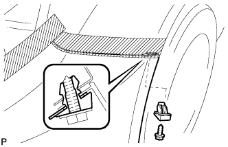
REMOVE ENGINE ROOM SIDE COVER LH
-
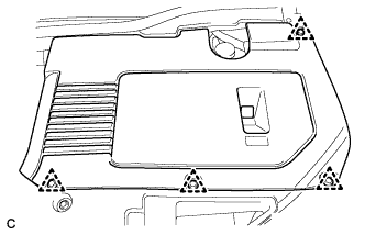
Remove the 4 clips and engine room side cover LH.
-
-
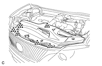
REMOVE ENGINE ROOM SIDE COVER
-
Remove the 4 clips and engine room side cover.
-
-
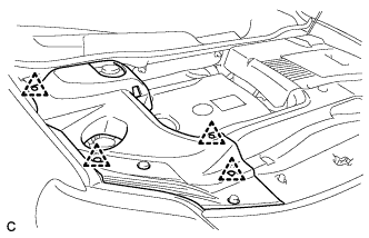
REMOVE COOL AIR INTAKE DUCT SEAL
-
Remove the 6 clips and cool air intake duct seal.
-
-
REMOVE NO. 1 ENGINE UNDER COVER
-
DRAIN COOLANT (for Engine)
Note
Do not remove the radiator cap, cylinder block drain cock plugs and radiator drain cock plug while the engine and radiator are still hot. Pressurized hot engine coolant and steam may be released and cause serious burns.
-
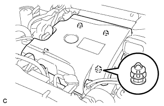
Loosen the radiator drain cock plug and drain the coolant.
Tech Tips
Collect the coolant in a container and dispose of it according to the regulations in your area.
-
Remove the radiator cap from the radiator assembly.
-
Loosen the 2 cylinder block drain cock plugs.
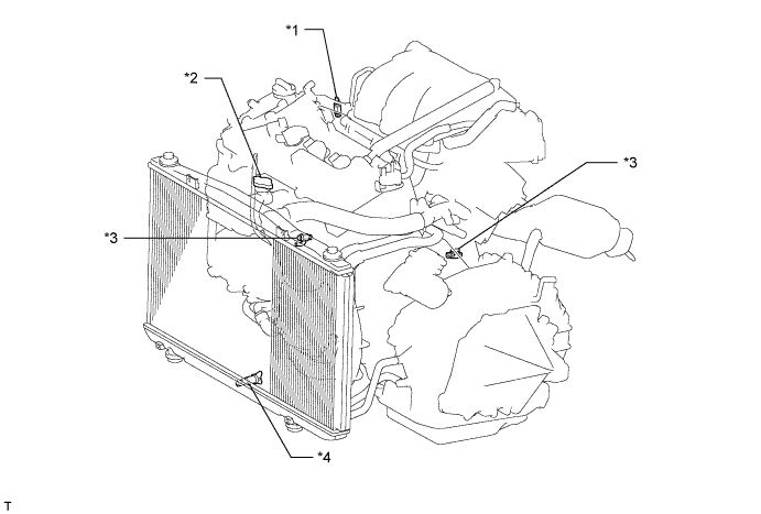
Text in Illustration *1 Air Drain Cock Plug *2 Radiator Cap *3 Cylinder Block Drain Cock Plug *4 Radiator Drain Cock Plug
-
-
REMOVE V-BANK COVER SUB-ASSEMBLY
-
Hold the front of the V-bank cover sub-assembly and raise it to disengage the 2 retainers on the front of the V-bank cover sub-assembly. Continue to raise the V-bank cover sub-assembly to disengage the 2 retainers on the rear of the V-bank cover sub-assembly and remove the V-bank cover sub-assembly.
Note
Attempting to disengage both front and rear retainers at the same time may cause the V-bank cover sub-assembly to break.
-
-
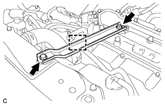
REMOVE INTAKE AIR RESONATOR SUB-ASSEMBLY
-
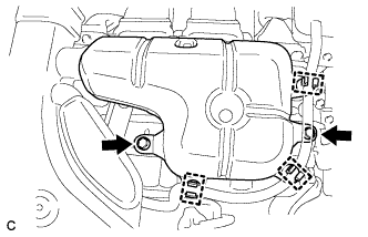
Remove the 3 clamps and Disconnect the water hose from the intake air resonator sub-assembly.
-
Remove the 2 bolts and intake air resonator sub-assembly from the inverter with converter assembly.
-
-
REMOVE NO. 2 AIR CLEANER INLET
-
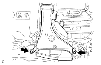
Remove the 2 bolts and inlet No. 2 air cleaner.
-
-
REMOVE NO. 1 AIR CLEANER INLET
-
Disconnect the No. 1 fuel vapor feed hose from the inlet No. 1 air cleaner.
-
Remove the bolt and inlet No. 1 air cleaner.
-
-
REMOVE NO. 3 INVERTER BRACKET
-
Disconnect the water hose clamp from the No. 3 inverter bracket.
-
Remove the bolt, nut and No. 3 inverter bracket.
-
-
REMOVE HOOD CUSHION CENTER
-
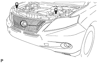
Remove the 2 hood center cushions.
-
-
REMOVE FRONT BUMPER ASSEMBLY
-
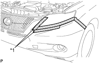
Text in Illustration *1 Protective Tape Put protective tape around the front bumper assembly.
Tech Tips
Use the same procedure for the RH side and LH side.
-
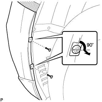
Using a screwdriver, turn the pins 90 degrees and remove the 2 pin hold clips.
Tech Tips
Use the same procedure for the RH side and LH side.
-
Remove the screw and front bumper seal bracket.
Tech Tips
Use the same procedure for the RH side and LH side.
-
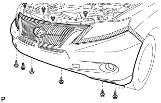
Remove the 2 bolts and 2 screws.
-
Using a clip remover, remove the 6 clips.
-
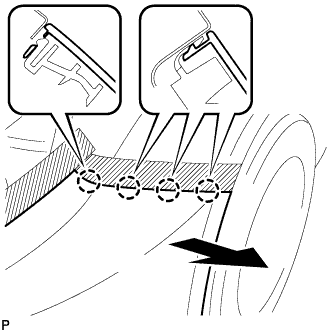
Disengage the 4 claws and remove the front bumper assembly.
Tech Tips
Use the same procedure for the RH side and LH side.
-
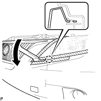
Using a moulding remover, disengage the claw.
Tech Tips
Use the same procedure for the RH side and LH side.
-
Disconnect the fog light connector.
-
Disconnect the No. 1 ultrasonic sensor connector. (w/ LEXUS Parking Assist-sensor System)
-
Disconnect the headlight cleaner hose.
Note
Prepare a drain pan or a piece of cloth in case washer fluid leaks.
-
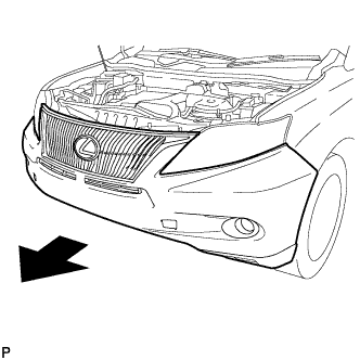
Remove the front bumper assembly as shown in the illustration.
-
-
REMOVE RADIATOR RESERVE TANK ASSEMBLY
-
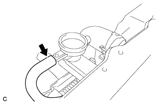
Disconnect the radiator reserve tank hose from the radiator.
-
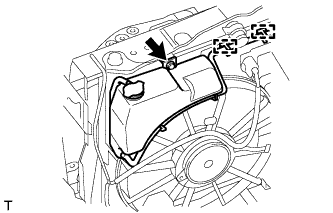
Disconnect the 2 clamps and remove the bolt and radiator reserve tank from the radiator.
-
-
DISCONNECT NO. 1 RADIATOR HOSE
-
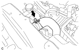
Disconnect the No. 1 radiator hose from the radiator.
-
-
DISCONNECT NO. 2 RADIATOR HOSE
-
Disconnect the No. 2 radiator hose from the radiator.
-
-
REMOVE MILLIMETER WAVE RADAR SENSOR ASSEMBLY (w/ Dynamic Radar Cruise Control System)
-
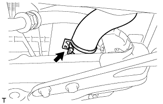
Disconnect the connector.
-
Remove the 3 bolts and the millimeter wave radar sensor assembly.
-
-
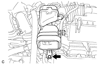
REMOVE LOW PITCHED HORN ASSEMBLY
-
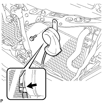
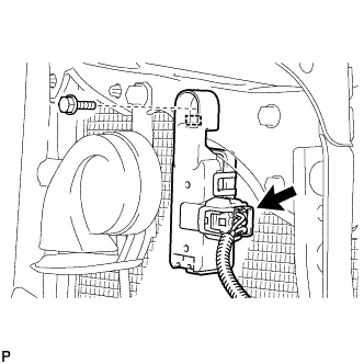
Disconnect the connector.
-
Remove the bolt and low pitched horn assembly.
-
-
REMOVE SMOG VENTILATION SENSOR (w/ Smog Ventilation Sensor)
-
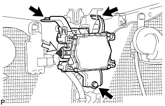
Disconnect the connector.
-
Remove the bolt
-
Disengage the guide and remove the smog ventilation sensor.
-
-
REMOVE HOOD LOCK CONTROL CABLE COVER (for LHD)
-
Remove the 3 screws.
-
Disengage the clamp and remove the hood lock control cable cover.
-
-
REMOVE HOOD LOCK ASSEMBLY (for LHD)
-
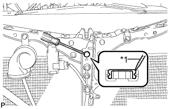
Text in Illustration *1 Protective Tape Using a screwdriver, remove the hood lock nut cap.
Tech Tips
Tape the screwdriver tip before use.
-
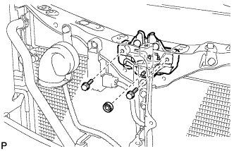
Remove the 2 bolts and hood lock nut.
-
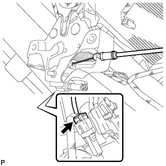
Disconnect the connector.
-
Disconnect the hood lock control cable and remove the hood lock assembly.
-
-
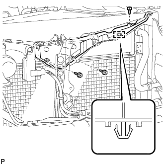
REMOVE UPPER RADIATOR SUPPORT
-
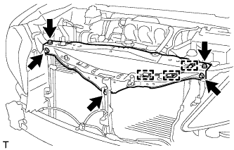
Disconnect the 3 clamps of the hood lock control cable and remove the 5 bolts and upper radiator support.
-
-
REMOVE NO. 2 RADIATOR ASSEMBLY
-
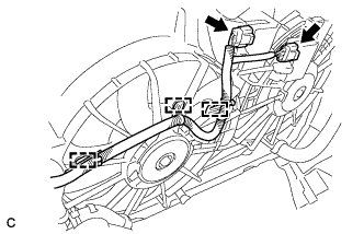
Disconnect the 3 wire harness clamps and 2 connectors.
-
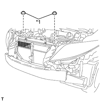
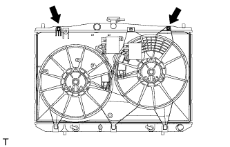
Text in Illustration *1 Radiator Support Cushion Remove the 2 radiator support cushions from the radiator.
-
Remove the 4 bolts.
-
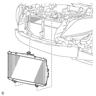
Remove the radiator assembly and fan assembly with motor.
Note
Do not apply any excessive force to the cooler condenser assembly or pipe when removing the radiator assembly.
-
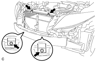
Remove the 2 lower radiator supports from the radiator.
-
Remove the 2 bolts.
-
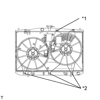
Text in Illustration *1 Claw *2 Guide Release the claw and pull up the fan assembly with motor from the radiator assembly to remove the fan assembly with motor.
-