FUEL INJECTOR REMOVAL

-
PRECAUTION (w/ Air Suspension)
Note
Be sure to read Precaution thoroughly before servicing Click here.
-
PRECAUTION (w/ Navigation System for HDD)
Note
After the power switch is turned off, the display and navigation module display (HDD navigation system) records various types of memory and settings. As a result, after turning the power switch off, make sure to wait for the time specified in the following table before disconnecting the cable from the negative (-) battery terminal.
Waiting Time before Disconnecting Cable from Negative (-) Battery Terminal Specification Waiting Time w/o Telematics transceiver 60 sec. w/ Telematics transceiver 120 sec. -
DISCHARGE FUEL SYSTEM PRESSURE
Tech Tips
-
REMOVE REAR DECK FLOOR BOX
-

Remove the 3 clips and the rear deck floor box.
-
-
DISCONNECT CABLE FROM NEGATIVE BATTERY TERMINAL
Note
When disconnecting the cable, some systems need to be initialized after the cable is reconnected Click here.
-
REMOVE AIR CLEANER ASSEMBLY WITH HOSE
Tech Tips
-
REMOVE INTAKE AIR SURGE TANK ASSEMBLY
-
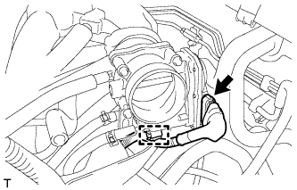
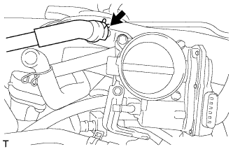
Disconnect the throttle body assembly connector and wire harness clamp.
-
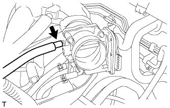
Disconnect the fuel vapor feed hose.
-
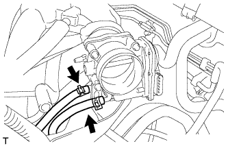
Disconnect the 2 water by-pass hoses.
-
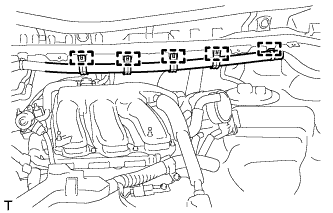
Disconnect the 5 clamps and separate the main wire.
-
Disconnect the ventilation hose.
-
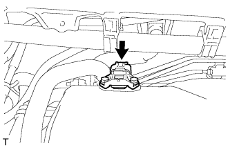
Disconnect the connector from the manifold absolute pressure sensor.
-

Remove the bolt and separate the No. 1 surge tank stay from the intake air surge tank assembly.
-
Remove the bolt and separate the throttle body bracket from the intake air surge tank assembly.
-
Remove the 2 nuts from the intake air surge tank assembly.
-
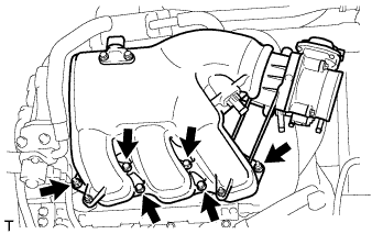
Using a 5 mm socket hexagon wrench, remove the 4 bolts.
-
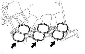
Remove the intake air surge tank assembly and 3 air surge tank to intake manifold gaskets.
-
-
REMOVE NO. 2 EGR PIPE
-
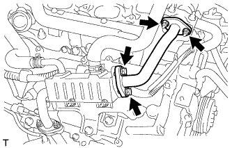
Remove the 2 nuts, 2 bolts, No. 2 EGR pipe and 2 gaskets. (Type A)
-
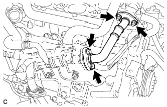
Remove the 2 nuts, 2 bolts, No. 2 EGR pipe and 2 gaskets. (Type B)
-
-
REMOVE EGR DELIVERY CHAMBER
-
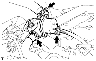
Disconnect the 2 water hoses and connector.
-
Remove the EGR delivery chamber.
-
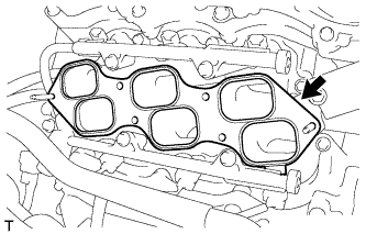
Remove the No. 2 intake manifold gasket.
-
-
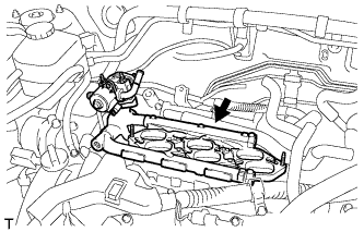
DISCONNECT FUEL TUBE SUB-ASSEMBLY
-
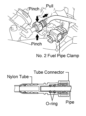
Remove the No. 2 fuel pipe clamp.
-
Pinch the tube connector and pull out the fuel pipe.
Note
-
Check that there is no dirt or other foreign objects around the connector when disconnecting it. Clean the connector as necessary.
-
It is necessary to prevent dirt or foreign objects from entering the quick connector. If dirt or foreign objects get in the connector, the O-rings may not seal properly.
-
Only disconnect the quick connector by hand.
-
Do not bend, kink or twist the nylon tubes.
-
Protect the connector by covering it with a plastic bag.
-
If the pipe and the connector are stuck, carefully try wiggling or pushing and pulling on the connector to release it. Pull the connector off carefully.
-
-
-
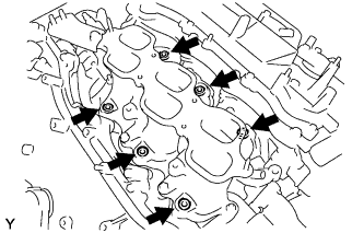
REMOVE FUEL INJECTOR ASSEMBLY
-
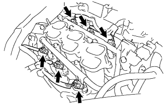
Disconnect the 6 fuel injector connectors.
-
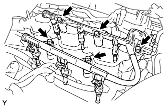
Remove the 5 bolts and fuel delivery pipe sub-assembly together with the 6 fuel injectors.
Note
Be careful not to drop the fuel injectors when removing the fuel delivery pipe.
-
Remove the 6 injector vibration insulators from the intake manifold.
-
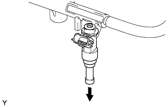
Pull out the fuel injectors from the fuel delivery pipe.
Note
If the injectors are to be reused, reinstall them to the same cylinder they came from.
-
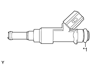
Text in Illustration *1 O-ring Remove the 6 O-rings from the injectors.
-