HV BATTERY INSTALLATION

-
INSTALL HYBRID BATTERY PACK WIRE
Tech Tips
Exchange the lower hybrid battery carrier panel as a set when liquids collect at the lower hybrid battery carrier panel and powder sticks.
-
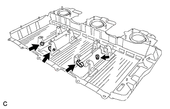
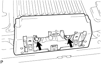
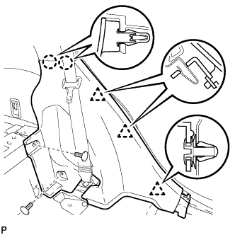
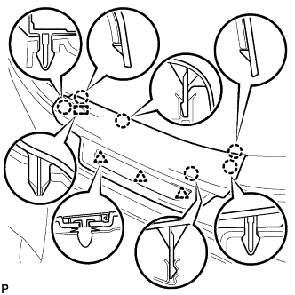
Install the 4 clamps to the hybrid battery carrier panel.
-
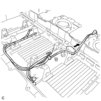
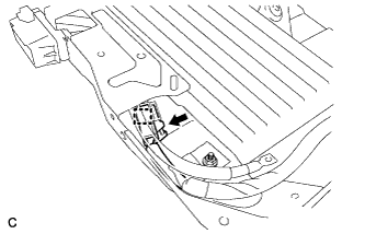
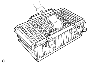
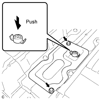
Install the battery pack wire to the lower hybrid battery carrier panel.
Tech Tips
Install the foam pad by pushing it in the direction shown in the illustration.
-
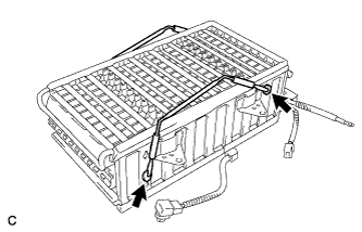
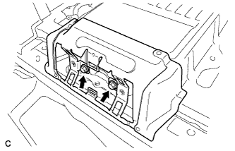
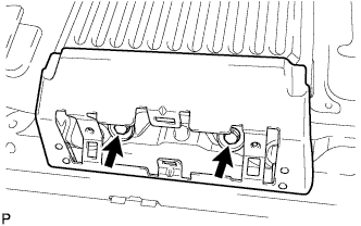
Connect the 3 clamps, then install the battery pack wire to the lower hybrid battery carrier panel.
-
-
INSTALL NO. 2 BATTERY PACKING
Tech Tips
Exchange the lower hybrid battery carrier panel as a set when liquids collect at the lower hybrid battery carrier panel and powder sticks.
-
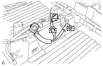
Install the No. 2 battery packing to the lower hybrid battery carrier panel.
Note
Make sure that there is no clearance between the battery packing and the lower carrier panel.
-
-
INSTALL HYBRID BATTERY CARRIER PANEL
Tech Tips
Exchange the lower hybrid battery carrier panel as a set when liquids collect at the lower hybrid battery carrier panel and powder sticks.
-
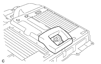
Install the lower hybrid battery carrier panel on the vehicle.
-
-
INSTALL HYBRID BATTERY JUNCTION BLOCK ASSEMBLY
Tech Tips
Exchange the lower hybrid battery carrier panel as a set when liquids collect at the lower hybrid battery carrier panel and powder sticks.
-
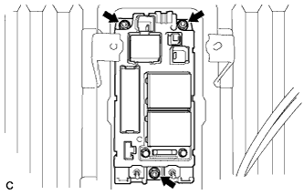
Install the hybrid battery junction block assembly with the 3 nuts.
- Torque:
- 7.5 N*m { 76 kgf*cm, 66 in.*lbf }
-
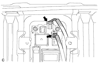
Connect the 2 connectors to the hybrid battery junction block assembly.
-
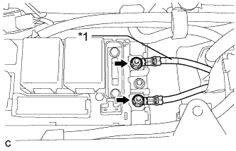
Text in Illustration *1 Red Tape Install the No. 3 wire frame to the hybrid battery junction block assembly with the 2 nuts.
- Torque:
- 9.0 N*m { 92 kgf*cm, 80 in.*lbf }
Note
-
Make sure that each end of the No. 3 wire frame does not cross over each other.
-
Be sure to connect the No. 3 wire frame to each correct terminal as shown in the illustration.
-
-
INSTALL ELECTRIC VEHICLE BATTERY PLUG ASSEMBLY
Tech Tips
Exchange the lower hybrid battery carrier panel as a set when liquids collect at the lower hybrid battery carrier panel and powder sticks.
-
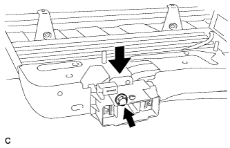
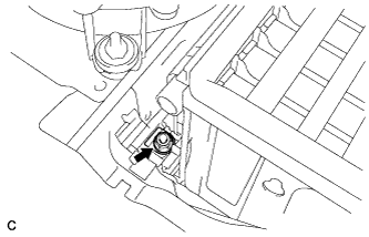
Install the electric vehicle battery plug assembly with the bolt.
- Torque:
- 7.5 N*m { 76 kgf*cm, 66 in.*lbf }
-
Connect the connector and clamp.
-
-
INSTALL BATTERY COOLING BLOWER ASSEMBLY
Tech Tips
Exchange the lower hybrid battery carrier panel as a set when liquids collect at the lower hybrid battery carrier panel and powder sticks.
-
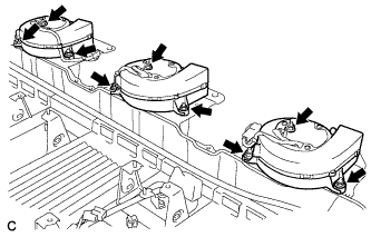
Install the 3 battery cooling blower assemblies with the 9 nuts.
- Torque:
- 7.5 N*m { 76 kgf*cm, 66 in.*lbf }
-
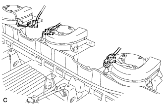
Connect each battery cooling blower assembly connector and 3 clamps.
-
-
INSTALL NO. 2 HV BATTERY PACK CABLE
Tech Tips
Exchange the lower hybrid battery carrier panel as a set when liquids collect at the lower hybrid battery carrier panel and powder sticks.
-
Install the No. 2 HV battery pack cable with the bolt.
- Torque:
- 7.5 N*m { 76 kgf*cm, 66 in.*lbf }
-
-
INSTALL HV BATTERY
CAUTION:
Be sure to wear insulated gloves and protective goggles.
-
Attach the HV battery name label. (If the lower carrier panel is not being replaced)
-
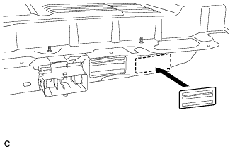
Attach the new label to the immediate right of the original one.
Tech Tips
An HV battery name label is supplied with the new battery.
-
-
Attach the HV battery name label. (If the lower carrier panel is being replaced)
-
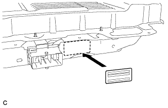
Attach the new label to the original position.
Tech Tips
An HV battery name label is supplied with the new battery.
-
-
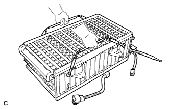
Install the HV battery module RH.
-
Install the carry belts to the HV battery module RH.
-
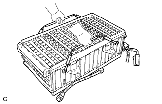
Install the HV battery module RH.
Note
After installing the HV battery module RH, remove the carry belts from the HV battery module RH.
-
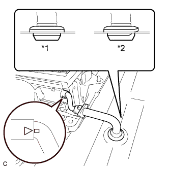
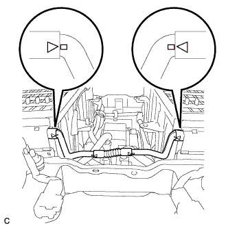
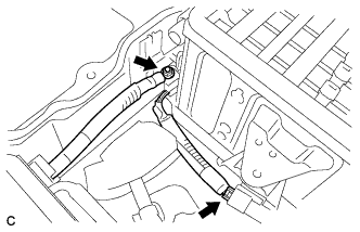
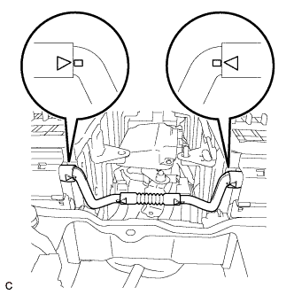
Text in Illustration *1 Correct *2 Incorrect Install the battery room ventilation hose.
Note
-
Make sure that there is no space or gap between the grommet and the body.
-
Align the projections of the battery room ventilation hose and the rubber tube, and install the hose.
-
-
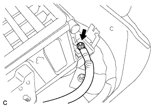
Connect the No. 2 HV battery pack cable to the HV battery module RH with a new nut.
- Torque:
- 5.4 N*m { 55 kgf*cm, 48 in.*lbf }
Note
-
Be sure to engage the plastic cover securely.
-
Insulate the tool with insulting tape.
-
Do not use a universal joint. Using a universal joint may cause the socket extension to drop and create a short circuit.
-
Connect the connector.
-
-
Install the center HV battery module.
-
Install the carry belts to the center HV battery module.
-
Install the center HV battery module.
Note
After installing the center HV battery module, remove the carry belts from the center HV battery module.
-
Install the battery room ventilation hose between the center HV battery module and the HV battery module RH.
Note
Align the projections of the battery room ventilation hose and the rubber tube, and install the hose.
-
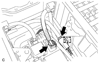
Connect the 2 connectors and clamp.
-
Connect the connector and clamp.
-
Connect the 2 wire harness clamps.
-
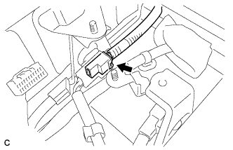
Connect the connector.
-
Connect the connector and clamp.
-
-
Install the HV battery module LH.
-
Install the carry belts to the HV battery module LH.
-
Install the HV battery module LH.
Note
After installing the HV battery module LH, remove the carry belts from the HV battery module LH.
-
Install the carry belts to the center HV battery module as shown in the illustration.
-
Connect the EV battery plug to the HV battery module LH with a new nut.
- Torque:
- 5.4 N*m { 55 kgf*cm, 48 in.*lbf }
Note
-
Be sure to engage the plastic cover securely.
-
Insulate the tool with insulting tape.
-
Do not use a universal joint. Using a universal joint may cause the socket extension to drop and create a short circuit.
-
Connect the main battery cable to the HV battery module LH with a new nut.
- Torque:
- 5.4 N*m { 55 kgf*cm, 48 in.*lbf }
Note
-
Be sure to engage the plastic cover securely.
-
Insulate the tool with insulting tape.
-
Do not use a universal joint. Using a universal joint may cause the socket extension to drop and create a short circuit.
-
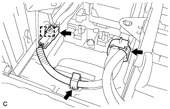
Connect the connector.
-
Connect the connector and clamp of the battery thermo sensor.
-
Connect the battery room ventilation hose between the HV battery module LH and the center HV battery module.
Note
Align the projections of the battery room ventilation hose and the rubber tube, and install the hose.
-
-
-
INSTALL BATTERY SMART UNIT
CAUTION:
Be sure to wear insulated gloves and protective goggles.
-
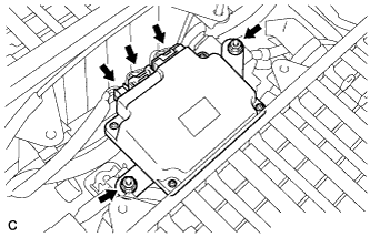
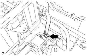
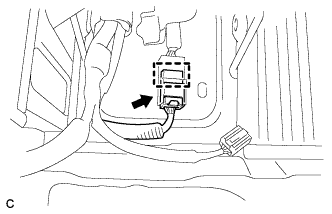
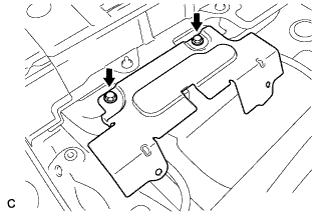
Install the battery smart unit with the 2 nuts.
- Torque:
- 7.5 N*m { 76 kgf*cm, 66 in.*lbf }
-
Connect the 3 connectors.
Note
The connectors should be connected securely.
-
-
CHECK HIGH VOLTAGE CABLE CONNECTION CONDITION
CAUTION:
Wear insulated gloves and protective goggles.
-
Check that each wire harness is being installed securely.
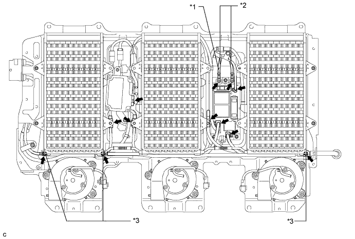
Text in Illustration *1 Red Tape *2 No. 3 Wire Frame *3 Plastic Cover - - Note
-
Make sure that the end of the No. 3 wire frame do not cross each other.
-
Be sure to connect the No. 3 wire frame to each correct terminal as shown in the illustration.
-
The connectors should be connected securely.
-
The nuts should be fastened securely.
-
Make sure that the 4 plastic covers are engaged securely.
-
-
-
INSTALL BATTERY COVER SUB-ASSEMBLY
CAUTION:
Wear insulated gloves.
-
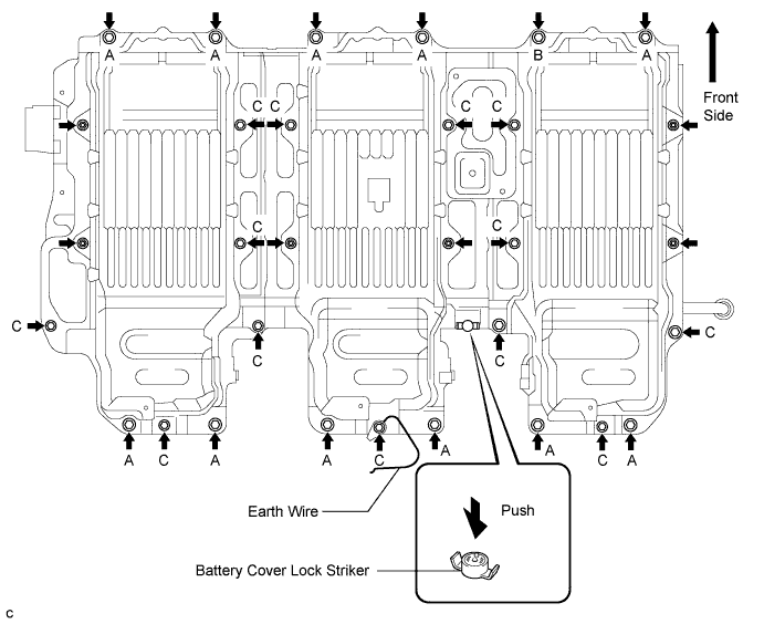
Install the battery cover lock striker, then push the button to lock.
-
Install the battery cover with the 25 bolts and 6 nuts.
Note
-
When installing the battery cover, check that the battery cooling blower assembly wire harness is not pinched before tightening the bolts and nuts that secure the cover.
-
Use a ground bolt for position B.
- Torque:
- Bolt A
- 25 N*m { 255 kgf*cm, 19 ft.*lbf }
- Bolt B
- 22 N*m { 224 kgf*cm, 16 ft.*lbf }
- Bolt C
- 7.5 N*m { 76 kgf*cm, 66 in.*lbf }
- Nut
- 7.5 N*m { 76 kgf*cm, 66 in.*lbf }
-
-
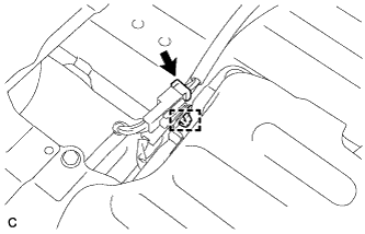
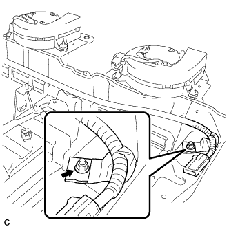
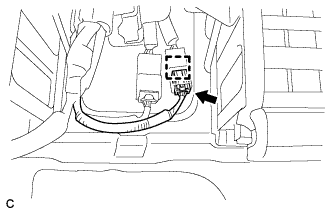
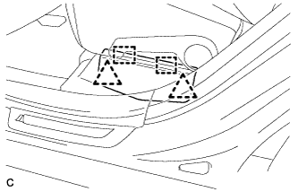
Connect the connector and clamp shown in the illustration.
-
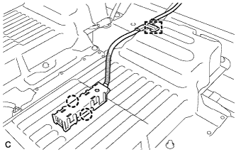
Connect the 2 claws and clamp, and install the indoor electrical key oscillator.
-
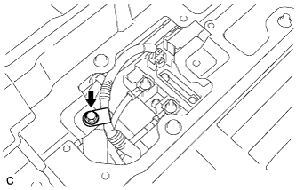
Connect the No. 3 wire frame with the bolt.
- Torque:
- 8.4 N*m { 86 kgf*cm, 74 in.*lbf }
-
-
INSTALL NO. 1 BATTERY COVER LID
-
Install the battery cover lock striker, then push the button to lock.
-
Install the No. 1 battery cover lid with the 2 bolts.
- Torque:
- 7.5 N*m { 76 kgf*cm, 66 in.*lbf }
-
-
INSTALL BATTERY CARRIER DUCT
-
Install the battery carrier duct RH with the 2 bolts.
- Torque:
- 7.5 N*m { 76 kgf*cm, 66 in.*lbf }
-
Install the battery carrier duct CTR with the 2 bolts.
- Torque:
- 7.5 N*m { 76 kgf*cm, 66 in.*lbf }
-
Install the battery carrier duct LH with the 2 bolts.
- Torque:
- 7.5 N*m { 76 kgf*cm, 66 in.*lbf }
-
-
INSTALL BATTERY CARRIER BRACKET
-
Install the battery carrier bracket with the 2 bolts.
- Torque:
- 7.5 N*m { 76 kgf*cm, 66 in.*lbf }
-
-
INSTALL FRONT FLOOR CARPET ASSEMBLY
-
Install the front floor carpet.
-
-
INSTALL AIR INTAKE COVER
-
Install the air intake cover RH.
-
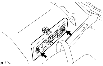
Install the air intake cover RH with the 2 claws and the 2 screws.
-
Install the 2 hole covers.
-
-
Install the air intake cover CTR.
-
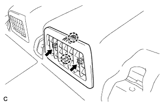
Install the air intake cover CTR with the 2 claws and the 2 screws.
-
Install the 2 hole covers.
-
-
Install the air intake cover LH.
-
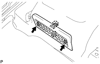
Install the air intake cover LH with the 2 claws and the 2 screws.
-
Install the 2 hole covers.
-
-
-
INSTALL REAR SEAT SIDE COVER LH
-
Engage the 2 claws and 3 clips.
-
Install the rear seat side cover LH with the 2 clips.
-
-
INSTALL REAR SEAT SIDE COVER RH
Tech Tips
Perform the same procedure as for the LH side.
-
INSTALL REAR DOOR SCUFF PLATE LH
-
Engage the 3 clips, guide and 6 claws, and install the rear door scuff plate LH.
-
-
INSTALL REAR DOOR SCUFF PLATE RH
Tech Tips
Perform the same procedure as for the LH side.
-
INSTALL REAR NO. 1 SEAT ASSEMBLY (for RH Side)
Tech Tips
-
INSTALL REAR NO. 1 SEAT ASSEMBLY (for LH Side)
Tech Tips
-
INSTALL SERVICE PLUG GRIP
CAUTION:
Wear insulated gloves.
Note
Before connecting the service plug, check that no parts and tools remain and that the high voltage terminals and connectors are connected securely.
-
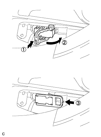
Wear insulated gloves and insert the service plug grip in the order shown in the illustration.
-
Tilt the service plug grip 90° and slide it down until a click sound is heard.
-
-
INSTALL BATTERY SERVICE HOLE COVER
-
Engage the 2 clips, 2 guides and install the battery service hole cover.
Note
Make sure that the battery service hole cover is installed securely.
-
-
CONNECT CABLE TO NEGATIVE BATTERY TERMINAL
-
PERFORM INITIALIZATION
Some systems need initialization after reconnecting the cable to the negative battery terminal Click here.