STEERING COLUMN ASSEMBLY INSTALLATION

-
INSTALL STEERING INTERMEDIATE SHAFT ASSEMBLY
-
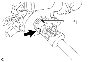
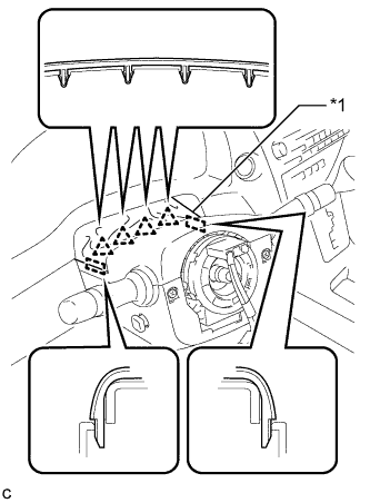
Text in Illustration *1 Matchmark Align the matchmarks on the steering intermediate shaft assembly and steering column assembly.
-
Install the bolt.
- Torque:
- 35 N*m { 360 kgf*cm, 26 ft.*lbf }
-
-
INSTALL STEERING POST ASSEMBLY
-
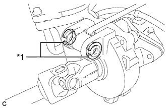
Text in Illustration *1 Bushing Check that the 2 bushings are securely installed to the steering column assembly.
Tech Tips
If the bushings are missing or damaged, replace the steering column assembly with a new one.
-
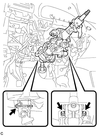
Install the steering post assembly with the bolt and 2 nuts.
- Torque:
- Bolt
- 36 N*m { 367 kgf*cm, 27 ft.*lbf }
- Nut
- 25 N*m { 255 kgf*cm, 18 ft.*lbf }
-
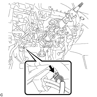
Engage the 2 wire harness clamps.
-
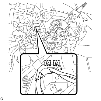
Connect the connectors and engage the wire harness clamps to the steering post assembly.
-
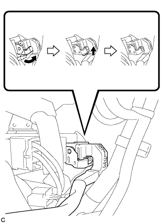
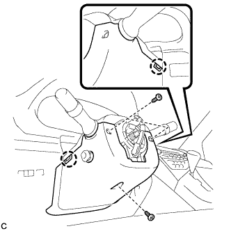
Connect the connector to the power steering ECU assembly.
Tech Tips
As shown in the illustration, securely return the lock lever to its original position to connect the connector.
-
Connect the connector to the power steering ECU assembly.
-
-
CONNECT STEERING INTERMEDIATE SHAFT ASSEMBLY
-
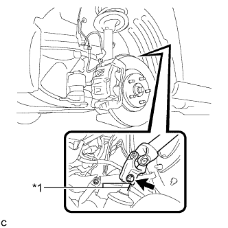
Text in Illustration *1 Matchmark Align the matchmarks on the steering intermediate shaft assembly and power steering link assembly.
-
Install the bolt.
- Torque:
- 35 N*m { 360 kgf*cm, 26 ft.*lbf }
-
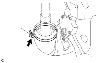
Install the steering intermediate shaft assembly to the steering column hole shield.
-
Tighten the bolt.
-
-
ALIGN FRONT WHEELS FACING STRAIGHT AHEAD
-
INSTALL TURN SIGNAL SWITCH ASSEMBLY WITH SPIRAL CABLE SUB-ASSEMBLY
-
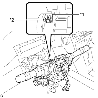
Text in Illustration *1 Clamp *2 Claw Using pliers, expand the clamp.
-
While holding the clamp expanded, install the turn signal switch assembly with spiral cable sub-assembly to the steering column assembly and engage the claw.
-
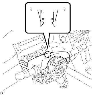
Return the clamp to its original position.
-
Connect the connectors to the turn signal switch assembly with spiral cable sub-assembly.
-
-
INSTALL STEERING COLUMN COVER
-
Engage the claw to install the upper steering column cover.
-
Engage the 2 claws to install the lower steering column cover to the upper steering column cover.
Note
Do not damage the tilt and telescopic switch.
-
Install the 3 screws.
- Torque:
- 2.0 N*m { 20 kgf*cm, 18 in.*lbf }
-
Text in Illustration *1 Instrument Panel Cluster Finish Panel Engage the 4 clips and 2 guides to install the instrument panel cluster finish panel to the upper steering column cover.
-
-
INSTALL BRAKE PEDAL SUPPORT ASSEMBLY (for LHD)
Tech Tips
Refer to the instructions for Installation of the brake pedal support assembly Click here.
-
INSTALL BRAKE PEDAL SUPPORT ASSEMBLY (for RHD)
Tech Tips
Refer to the instructions for Installation of the brake pedal support assembly Click here.
-
ALIGN FRONT WHEELS FACING STRAIGHT AHEAD
-
ADJUST SPIRAL CABLE WITH SENSOR SUB-ASSEMBLY
-
Check that the power switch is off.
-
Check that the cable is disconnected from the negative (-) battery terminal.
CAUTION:
Wait at least 90 seconds after disconnecting the cable from the negative (-) battery terminal to disable the SRS system.
-
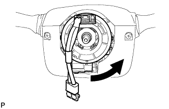
Rotate the spiral cable counterclockwise slowly by hand until it stops.
Note
Do not turn the spiral cable using the airbag wire harness.
-
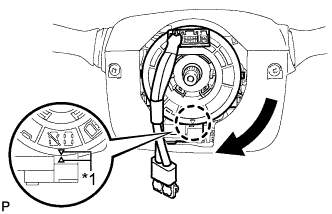
Text in Illustration *1 Alignment Mark Rotate the spiral cable clockwise approximately 2.5 turns to align the marks.
Note
Do not turn the spiral cable using the airbag wire harness.
Tech Tips
The spiral cable will rotate approximately 2.5 turns to both the left and right from the center.
-
-
INSTALL STEERING WHEEL ASSEMBLY
-
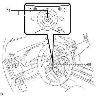
Text in Illustration *1 Matchmark Align the matchmarks on the steering wheel assembly and steering main shaft.
-
Install the steering wheel assembly set nut.
- Torque:
- 50 N*m { 510 kgf*cm, 37 ft.*lbf }
-
Connect the connectors to the spiral cable sub-assembly.
-
-
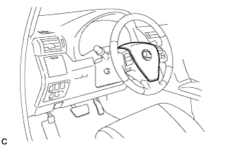
INSTALL STEERING PAD
Tech Tips
Refer to the instructions for Installation of the steering pad Click here.
-
INSTALL FRONT WHEEL LH
- Torque:
- 103 N*m { 1050 kgf*cm, 76 ft.*lbf }
-
ALIGN FRONT WHEELS FACING STRAIGHT AHEAD
-
CONNECT CABLE TO NEGATIVE BATTERY TERMINAL
Note
-
Make sure that the cable has been disconnected from the battery terminal for at least 2 seconds before reconnecting the cable.
-
Connect the cable to the negative (-) battery terminal with the front wheels facing straight ahead.
-
Reset the auto away/return function setting to the previous condition by changing the customize parameter Click here.
-
When disconnecting the cable, some systems need to be initialized after the cable is reconnected Click here.
-
-
INSTALL REAR DECK FLOOR BOX
-

Install the rear deck floor box with the 3 clips.
-
-
INSPECT STEERING PAD
-
Visually check for defects with the steering pad installed on the vehicle.
-
The defects are as follows:
-
Cuts on the surface and in the grooves of the steering pad
-
Small cracks on the surface and in the grooves of the steering pad
-
Significant discoloration on the surface and in the grooves of the steering pad
OK No defects are found. Tech Tips
If any of the defects is found, replace the steering pad with a new one.
-
-
-
Make sure that the horn sounds.
Tech Tips
If the horn does not sound, inspect the horn system Click here.
-
-
PERFORM DIAGNOSTIC SYSTEM CHECK
-
INSPECT SRS WARNING LIGHT
-
Inspect the SRS warning light Click here.
-