BRAKE PEDAL (for LHD) INSTALLATION

-
INSTALL BRAKE PEDAL SUPPORT ASSEMBLY
-
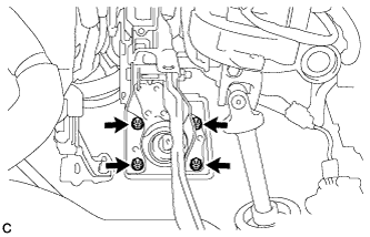
Install the brake pedal support assembly with the 4 nuts.
- Torque:
- 13 N*m { 130 kgf*cm, 9 ft.*lbf }
-
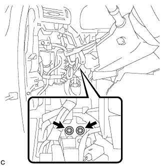
Install the brake pedal support assembly to the instrument panel reinforcement with the 2 bolts.
- Torque:
- 35 N*m { 357 kgf*cm, 26 ft.*lbf }
-
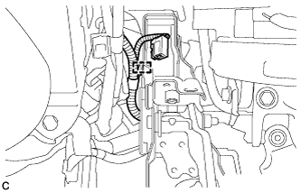
Engage the clamp.
-
-
CONNECT MASTER CYLINDER PUSH ROD CLEVIS
-
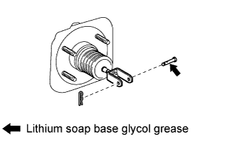
Apply lithium soap base glycol grease to the push rod pin.
-
Connect the master cylinder push rod clevis to the brake pedal with the push rod pin, and install a new clip as shown in the illustration.
-
-
INSTALL BRAKE PEDAL RETURN SPRING
-
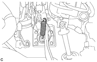
Install the brake pedal return spring between the brake pedal support sub-assembly and push rod pin.
-
-
INSTALL BRAKE PEDAL STROKE SENSOR ASSEMBLY
Note
Do not drop the sensor. If the sensor has been dropped, replace the brake pedal stroke sensor with a new one.
-
When installing a new brake pedal stroke sensor assembly:
Note
Do not break the sensor lever set pin before installing the brake pedal stroke sensor with the bolts.
-
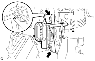
Text in Illustration *1 Lever *2 Groove Install a new sensor with the 2 bolts.
- Torque:
- 8.5 N*m { 87 kgf*cm, 75 in.*lbf }
Note
-
Engage the sensor lever with the brake pedal groove.
-
Check that there is no foreign matter attached to the contact surface of the sensor.
-
Check that the tip of the sensor lever is protruding from the brake pedal groove.
-
Firmly depress the brake pedal and break the sensor lever set pin.
-
Remove the broken lever set pin.
-
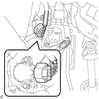
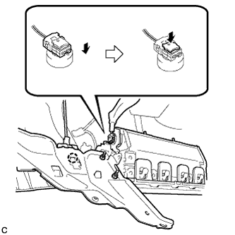
Connect the sensor connector.
-
-
When reusing the brake pedal stroke sensor assembly:
-
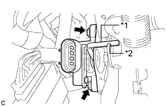
Text in Illustration *1 Lever *2 Groove Temporarily install the sensor with the 2 bolts.
Note
-
Engage the sensor lever with the brake pedal groove.
-
Check that there is no foreign matter attached to the contact surface of the sensor.
-
-
-
-
INSTALL STOP LIGHT SWITCH ASSEMBLY
-
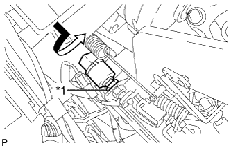
Text in Illustration *1 Lock Nut Temporarily install the stop light switch assembly with the stop light switch lock nut.
-
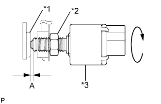
Text in Illustration *1 Cushion *2 Stop Light Switch Lock Nut *3 Stop Light Switch Turn the stop light switch assembly so that the clearance between the nut end and stop light switch cushion is between A.
Standard Clearance Area Measurement A 0.5 to 2.4 mm (0.0197 to 0.0945 in.) -
Tighten the stop light switch lock nut.
- Torque:
- 17 N*m { 170 kgf*cm, 12 ft.*lbf }
-
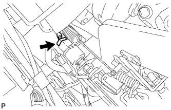
Connect the connector.
-
-
INSTALL NO. 4 AIR DUCT SUB-ASSEMBLY
-
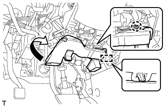
Engage the guide and claw to install the No. 4 air duct sub-assembly.
Note
Do not damage the claw or guide.
-
-
INSTALL DRIVER SIDE KNEE AIRBAG ASSEMBLY
-
Check that the power switch is off.
-
Check that the cable is disconnected from the negative (-) battery terminal.
CAUTION:
Wait at least 90 seconds after disconnecting the cable from the negative (-) battery terminal to disable the SRS system.
-
Engage the claw to connect the hood lock control cable to the driver side knee airbag assembly.
-
Connect the airbag connector to the driver side knee airbag assembly.
Note
When connecting any airbag connector, take care not to damage the airbag wire harness.
-
Temporarily install the driver side knee airbag assembly with the 2 claws and 2 hooks.
-
Install the driver side knee airbag assembly with the 4 bolts.
- Torque:
- 10 N*m { 102 kgf*cm, 7 ft.*lbf }
Note
Confirm that the driver side knee airbag assembly is installed securely without any excessive gaps and is not protruding outward.
-
-
INSTALL LOWER INSTRUMENT PANEL FINISH PANEL SUB-ASSEMBLY
-
Connect each connector.
-

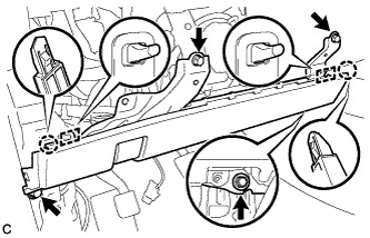
Engage the 8 clips and 2 guides.
-
Install the lower instrument panel finish panel sub-assembly with the 2 screws <D>.
-
Engage the 2 claws to close the cover as shown in the illustration.
-
-
INSTALL NO. 1 SWITCH HOLE BASE
-
Connect each connector.
-
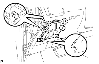
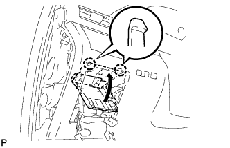
Engage the 4 claws and 2 guides to install the No. 1 switch hole base.
-
-
INSTALL INSTRUMENT PANEL GARNISH LH
-
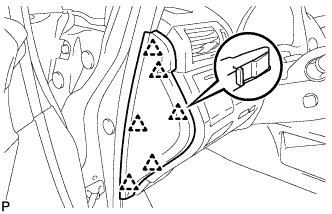
Engage the 6 clips to install the instrument panel garnish LH.
-
-
INSTALL NO. 1 INSTRUMENT PANEL UNDER COVER SUB-ASSEMBLY
-
Engage each clamp.
-
Connect each connector.
-
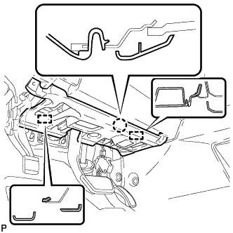
Engage the claw and 2 guides.
-

Install the No. 1 instrument panel under cover sub- assembly with the 2 screws <D>.
-
-
INSTALL COWL SIDE TRIM SUB-ASSEMBLY LH
-
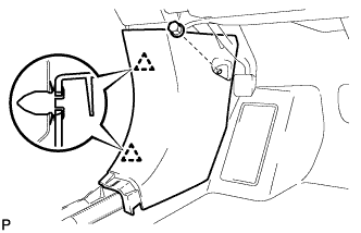
Engage the 2 clips to install the cowl side trim sub-assembly LH.
-
Install the clip.
-
-
INSTALL FRONT DOOR SCUFF PLATE LH
-
w/ Illumination:
-
Connect the connector.
-
-
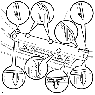
Engage the 4 clips, guide and 7 claws, and install the front door scuff plate LH.
-
-
CONNECT CABLE TO NEGATIVE BATTERY TERMINAL
Note
When disconnecting the cable, some systems need to be initialized after the cable is reconnected Click here.
-
INSTALL REAR DECK FLOOR BOX
-

Install the rear deck floor box with the 3 clips.
-
-
INSPECT AND ADJUST BRAKE PEDAL
Tech Tips
-
PERFORM LINEAR VALVE OFFSET LEARNING
Tech Tips
-
INSPECT SRS WARNING LIGHT
Tech Tips
-
INSPECT SUSPENSION CONTROL SYSTEM (w/ Air Suspension)
Tech Tips