FRONT SPEED SENSOR REMOVAL

Tech Tips
-
Use the same procedure for the LH side and RH side.
-
The following procedure is for the LH side.
-
If the sensor rotor needs to be replaced, replace it together with the front drive shaft assembly.
-
PRECAUTION (w/ Navigation System for HDD)
Note
After the power switch is turned off, the display and navigation module display (HDD navigation system) records various types of memory and settings. As a result, after turning the power switch off, make sure to wait for the time specified in the following table before disconnecting the cable from the negative (-) battery terminal.
Waiting Time before Disconnecting Cable from Negative (-) Battery Terminal Specification Waiting Time w/o Telematics transceiver 60 sec. w/ Telematics transceiver 120 sec. -
PRECAUTION (w/ Air Suspension)
Note
Be sure to read Precaution thoroughly before servicing Click here.
-
REMOVE REAR DECK FLOOR BOX
-

Remove the 3 clips and the rear deck floor box.
-
-
DISCONNECT CABLE FROM NEGATIVE BATTERY TERMINAL
Note
When disconnecting the cable, some systems need to be initialized after the cable is reconnected Click here.
-
REMOVE FRONT WHEEL
-
REMOVE FRONT SPEED SENSOR
-
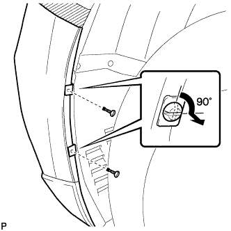
Using a screwdriver, turn the pins 90 degrees and remove the 2 pin hold clips.
Tech Tips
Use the same procedure for the RH side and LH side.
-
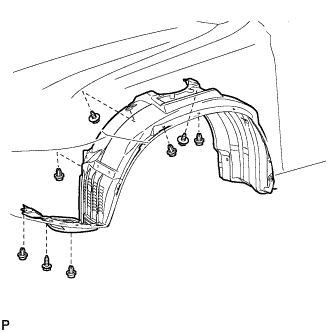
Remove the 5 clips and 3 screws, and turn back the front fender liner.
-
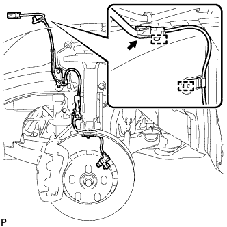
Disconnect the front speed sensor connector and remove the 2 clamps.
-
Text in Illustration *1 No. 2 Sensor Clamp Remove the bolt and No. 2 sensor clamp from the body.
-
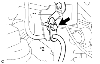
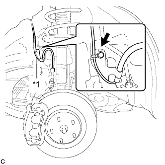
Text in Illustration *1 No. 1 Sensor Clamp *2 Front Brake Flexible Hose Remove the bolt, No. 1 sensor clamp and front brake flexible hose together from the shock absorber assembly.
-
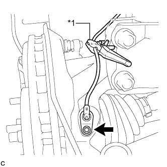
Text in Illustration *1 Resin Clamp Remove the bolt, resin clamp and front speed sensor.
Note
-
Prevent foreign matter from attaching to the front speed sensor tip.
-
Clean the speed sensor installation hole and the contact surfaces every time the front speed sensor is removed.
-
-