ELECTRONICALLY CONTROLLED BRAKE SYSTEM TC and CG Terminal Circuit
DESCRIPTION
Connecting terminals TC and CG of the DLC3 causes the ECU to display the DTC by blinking the ABS warning light.
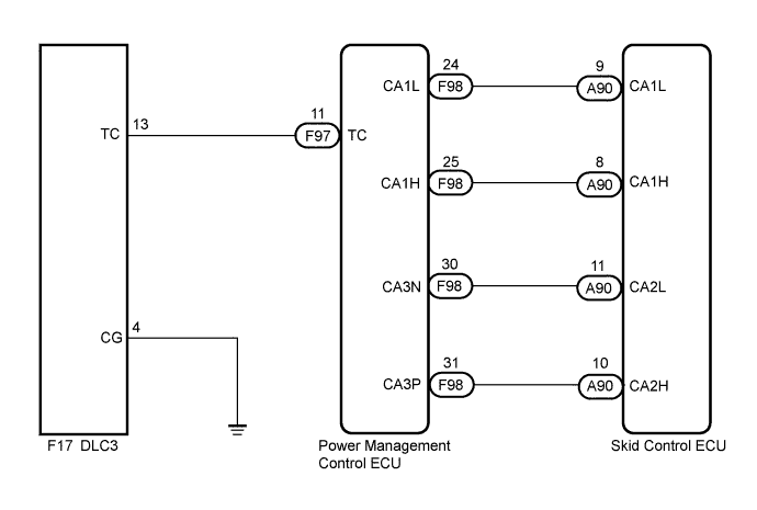
WIRING DIAGRAM
Tech Tips
When the warning lights continue to blink, a ground short in the wiring of terminal TC of the DLC3 or an internal ground short in one or more ECUs is suspected.
INSPECTION PROCEDURE
Note
When replacing the skid control ECU, perform initialization and calibration of the linear solenoid valve Click here.
PROCEDURE
-
CHECK CAN COMMUNICATION SYSTEM
-
Check if a CAN communication system DTC is output Click here.
Result Result Proceed to DTC is not output A DTC is output B
B 
INSPECT CAN COMMUNICATION SYSTEM Click here
A 
-
-
CHECK HARNESS AND CONNECTOR (TC of DLC3 - POWER MANAGEMENT CONTROL ECU)
-
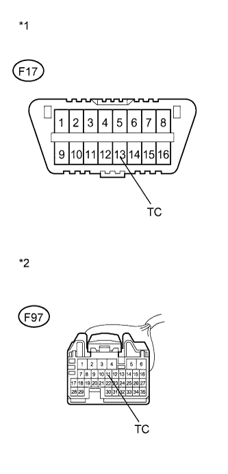
Text in Illustration *1 Front view of DLC3 *2 Front view of wire harness connector
(to Power Management Control ECU)
Disconnect the power management control ECU connector.
-
Measure the resistance according to the value(s) in the table below.
Standard Resistance Tester Connection Condition Specified Condition F17-13 (TC) - F97-11 (TC) Always Below 1 Ω
NG
REPAIR OR REPLACE HARNESS OR CONNECTOR
OK
-
-
CHECK HARNESS AND CONNECTOR (CG of DLC3 - BODY GROUND)
-
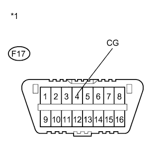
Text in Illustration *1 Front view of DLC3 Measure the resistance according to the value(s) in the table below.
Standard Resistance Tester Connection Condition Specified Condition F17-4 (CG) - Body ground Always Below 1 Ω
NG
REPAIR OR REPLACE HARNESS OR CONNECTOR
OK
-
-
CHECK HARNESS AND CONNECTOR (TC of DLC3 - BODY GROUND)
-
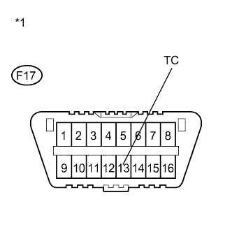
Text in Illustration *1 Front view of DLC3 Measure the resistance according to the value(s) in the table below.
Standard Resistance Tester Connection Condition Specified Condition F17-13 (TC) - Body ground Always 10 kΩ or higher Tech Tips
If troubleshooting has been carried out according to Problem Symptoms Table, refer back to the table and proceed to the next step before replacing the part Click here.
NG
REPAIR OR REPLACE WIRE HARNESS OR EACH ECU
OK 
REPLACE SKID CONTROL ECU Click here
-