СИСТЕМА БЕССТУПЕНЧАТОЙ ТРАНСМИССИИ, Diagnostic DTC:P0840, P0842, P0843
| DTC Code | DTC Name |
|---|---|
| P0840 | Transmission Fluid Pressure Sensor/Switch "A" Circuit |
| P0842 | Transmission Fluid Pressure Sensor/Switch "A" Circuit Low |
| P0843 | Transmission Fluid Pressure Sensor/Switch "A" Circuit High |
DESCRIPTION
The ECM performs learning control for the belt clamping pressure, based on the belt clamping pressure signal, which is detected by the oil pressure sensor.
| DTC No. | DTC Detection Condition
|
Trouble Area |
|---|---|---|
| P0840 |
|
|
| P0842 |
|
|
| P0843 |
|
|
MONITOR DESCRIPTION
These DTCs indicate an open or short in the oil pressure sensor. When there is an open or short circuit in oil pressure sensor circuits, the ECM detects the problem, illuminates the MIL and stores the DTC.
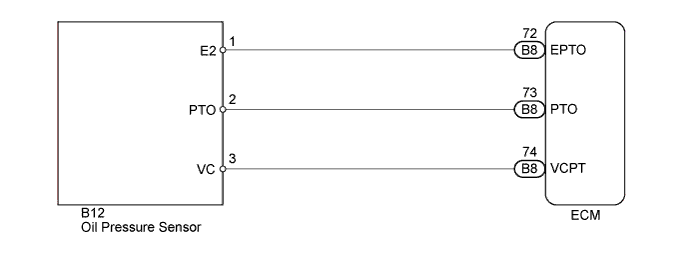
WIRING DIAGRAM
INSPECTION PROCEDURE
PROCEDURE
-
READ VALUE USING INTELLIGENT TESTER (A/T OIL PRESSURE)
-
Connect the intelligent tester to the DLC3.
-
Turn the ignition switch to ON.
-
Turn the tester on.
-
Enter the following menus: Powertrain / Engine and ECT / Data List.
-
In accordance with the display on the tester, read the Data List.
Tester Display Measurement Item/Range Normal Condition Diagnostic Note A/T Oil Pressure Secondary oil pressure value/
min.: -0.625 MPa
max.: 9.575 MPa
Secondary oil pressure inspection (D position stall test)
3.81 to 4.58 MPa
- Result Result Proceed to Data display is not within Normal Condition range A Data display is within Normal Condition range B
B 
REPLACE ECM Click here
A 
-
-
CHECK HARNESS AND CONNECTOR (OIL PRESSURE SENSOR - ECM)
-
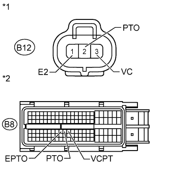
Text in Illustration *1 Front view of wire harness connector:
(to Oil Pressure Sensor)
*2 Front view of wire harness connector:
(to ECM)
Disconnect the oil pressure sensor connector.
-
Disconnect the ECM connector.
-
Measure the resistance according to the value(s) in the table below.
Standard Resistance Tester Connection Condition Specified Condition B12-1 (E2) - B8-72 (EPTO) Always Below 1 Ω B12-2 (PTO) - B8-73 (PTO) Always Below 1 Ω B12-3 (VC) - B8-74 (VCPT) Always Below 1 Ω B8-72 (EPTO) - Body ground Always 10 kΩ or higher B8-73 (PTO) - Body ground Always 10 kΩ or higher B8-74 (VCPT) - Body ground Always 10 kΩ or higher
NG 
REPAIR OR REPLACE HARNESS OR CONNECTOR
OK
-
-
INSPECT ECM (VCPT TERMINAL VOLTAGE)
-
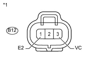
Text in Illustration *1 Front view of wire harness connector:
(to Oil Pressure Sensor)
Connect the ECM connector.
-
Turn the ignition switch to ON.
-
Measure the voltage according to the value(s) in the table below.
Standard Voltage Tester Connection Switch Condition Specified Condition B12-1 (E2) - B12-3 (VC) Ignition switch ON 4.5 to 5.5 V
NG
REPLACE ECM Click here
OK
-
-
REPLACE OIL PRESSURE SENSOR
-
Replace the oil pressure sensor Click here.
NEXT
-
-
PERFORM INITIALIZATION
Note
-
Performing reset memory/initialization will clear the learned values of both the yaw rate and acceleration sensor (deceleration sensor 0 point calibration) and the CVT oil pressure (CVT oil pressure calibration). Make sure to perform reset memory, yaw rate and acceleration sensor 0 point calibration, and CVT oil pressure calibration when replacing any of the parts shown in the following table:
Replaced Part
-
Continuously variable transaxle assembly
-
ECM
-
Oil pressure sensor
-
Yaw rate and acceleration sensor
-
-
After reset memory, always perform yaw rate and acceleration sensor (deceleration sensor 0 point) calibration first, and then the CVT oil pressure calibration.
-
Always perform the 0 point calibration with the vehicle on level ground.
-
Do not shake or vibrate the vehicle during the 0 point calibration.
-
Using the intelligent tester, perform the reset memory, deceleration sensor 0 point calibration and CVT oil pressure calibration Click here.
-
Check for DTCs again Click here.
NEXT 
END
-
-
REPLACE ECM
-
Replace the ECM Click here.
NEXT
-
-
PERFORM INITIALIZATION
Note
-
Performing reset memory/initialization will clear the learned values of both the yaw rate and acceleration sensor (deceleration sensor 0 point calibration) and the CVT oil pressure (CVT oil pressure calibration). Make sure to perform reset memory, yaw rate and acceleration sensor 0 point calibration, and CVT oil pressure calibration when replacing any of the parts shown in the following table:
Replaced Part
-
Continuously variable transaxle assembly
-
ECM
-
Oil pressure sensor
-
Yaw rate and acceleration sensor
-
-
After reset memory, always perform yaw rate and acceleration sensor (deceleration sensor 0 point) calibration first, and then the CVT oil pressure calibration.
-
Always perform the 0 point calibration with the vehicle on level ground.
-
Do not shake or vibrate the vehicle during the 0 point calibration.
-
Using the intelligent tester, perform the reset memory, deceleration sensor 0 point calibration and CVT oil pressure calibration Click here.
-
Check for DTCs again Click here.
NEXT
END
-