СИСТЕМА SFI, Diagnostic DTC:P0403
| DTC Code | DTC Name |
|---|---|
| P0403 | Exhaust Gas Recirculation Control Circuit |
DESCRIPTION
Refer to DTC P0401 Click here.
| DTC No. | DTC Detection Condition | Trouble Area |
|---|---|---|
| P0403 | Open or short in EGR valve circuit (1-trip detection logic) |
|
Tech Tips
DTC P0403 is set when the ignition switch is in the ON position.
WIRING DIAGRAM
Refer to DTC P0401 Click here.
INSPECTION PROCEDURE
Tech Tips
Read freeze frame data using an intelligent tester. The ECM records vehicle and driving condition information as freeze frame data the moment a DTC is stored. When troubleshooting, freeze frame data can help determine if the vehicle was moving or stationary, if the engine was warmed up or not, if the air-fuel ratio was lean or rich, and other data from the time the malfunction occurred.
PROCEDURE
-
PERFORM ACTIVE TEST USING INTELLIGENT TESTER (OPERATE EGR VALVE)
-
Connect the intelligent tester to the DLC3.
-
Turn the ignition switch to ON.
-
Turn the tester on.
-
Enter the following menus: Powertrain / Engine and ECT / Active Test / Control the EGR Step Position.
-
Perform the Active Test by referring to the table below.
Standard Tester Operation Condition Specified Condition 0 steps Idling Map value is 31 kPa with steady idling 0 to 30 steps Idling Map value is at least +10 to 15 kPa higher than when EGR valve is fully closed, and engine changes from steady to rough idling 30 steps or higher Idling Engine changes from rough idling to engine stall Result Result Proceed to Outside standard range A Within standard range B
NG 
INSPECT EGR VALVE ASSEMBLY Click here
OK 
CHECK FOR INTERMITTENT PROBLEMS Click here
-
-
INSPECT EGR VALVE ASSEMBLY
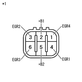
Text in Illustration *1 Component without harness connected:
(EGR Valve Assembly)
-
Disconnect the EGR valve assembly connector.
-
Measure the resistance according to the value(s) in the table below.
Standard Resistance Tester Connection Condition Specified Condition 2 (+B1) - 1 (EGR4) 20 °C (68 °F) 18 to 22 Ω 2 (+B1) - 3 (EGR2) 20 °C (68 °F) 18 to 22 Ω 5 (+B2) - 4 (EGR1) 20 °C (68 °F) 18 to 22 Ω 5 (+B2) - 6 (EGR3) 20 °C (68 °F) 18 to 22 Ω -
Reconnect the EGR valve assembly connector.
NG 
REPLACE EGR VALVE ASSEMBLY Click here
OK 
-
-
INSPECT EGR VALVE ASSEMBLY (+B OR +B2 VOLTAGE)
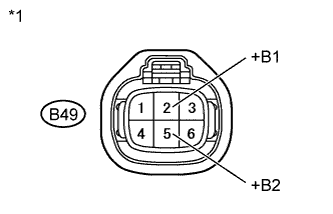
Text in Illustration *1 Front view of wire harness connector:
(to EGR Valve Assembly)
-
Disconnect the EGR valve assembly connector.
-
Measure the voltage according to the value(s) in the table below.
Standard Voltage Tester Connection Switch Condition Specified Condition B49-2 (+B1) - Body ground Ignition switch ON 11 to 14 V B49-5 (+B2) - Body ground Ignition switch ON 11 to 14 V -
Reconnect the EGR valve assembly connector.
NG
CHECK HARNESS AND CONNECTOR (INTEGRATION RELAY - EGR VALVE ASSEMBLY) Click here
OK
-
-
CHECK HARNESS AND CONNECTOR (ECM - EGR VALVE ASSEMBLY)
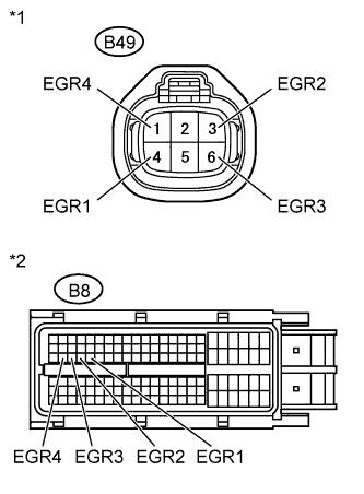
Text in Illustration *1 Front view of wire harness connector:
(to EGR Valve Assembly)
*2 Front view of wire harness connector:
(to ECM)
-
Disconnect the EGR valve assembly connector.
-
Disconnect the ECM connector.
-
Measure the resistance according to the value(s) in the table below.
Standard Resistance (Check for Open) Tester Connection Condition Specified Condition B8-51 (EGR1) - B49-4 (EGR1) Always Below 1 Ω B8-50 (EGR2) - B49-3 (EGR2) Always Below 1 Ω B8-49 (EGR3) - B49-6 (EGR3) Always Below 1 Ω B8-48 (EGR4) - B49-1 (EGR4) Always Below 1 Ω Standard Resistance (Check for Short) Tester Connection Condition Specified Condition B8-51 (EGR1) or B49-4 (EGR1) - Body ground Always 10 kΩ or higher B8-50 (EGR2) or B49-3 (EGR2) - Body ground Always 10 kΩ or higher B8-49 (EGR3) or B49-6 (EGR3) - Body ground Always 10 kΩ or higher B8-48 (EGR4) or B49-1 (EGR4) - Body ground Always 10 kΩ or higher -
Reconnect the EGR valve assembly connector.
-
Reconnect the ECM connector.
NG
REPAIR OR REPLACE HARNESS OR CONNECTOR
OK
-
-
READ DTC OUTPUT RECURS (DTC P0403)
-
Connect the intelligent tester to the DLC3.
-
Turn the ignition switch to ON and turn the tester on.
-
Clear DTCs Click here.
-
Start the engine warm it up.
-
Drive the vehicle for more than 10 minutes.
-
Confirm on the vehicle that no DTC is set using the intelligent tester.
Result Result Proceed to P0403 A No output B
B
END
A
REPLACE ECM Click here
-
-
CHECK HARNESS AND CONNECTOR (INTEGRATION RELAY - EGR VALVE ASSEMBLY)
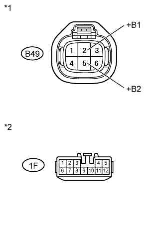
Text in Illustration *1 Front view of wire harness connector:
(to EGR Valve Assembly)
*2 Front view of wire harness connector:
(to Integration Relay)
-
Disconnect the EGR valve assembly connector.
-
Remove the integration relay from engine room relay block.
-
Measure the resistance according to the value(s) in the table below.
Standard Resistance (Check for open) Tester Connection Condition Specified Condition 1F-10 - B49-2 (+B1) Always Below 1 Ω 1F-11 - B49-5 (+B2) Always Below 1 Ω Standard Resistance (Check for short) Tester Connection Condition Specified Condition 1F-10 or B49-2 (+B1) - Body ground Always 10 kΩ or higher 1F-11 or B49-5 (+B2) - Body ground Always 10 kΩ or higher -
Reconnect the EGR valve assembly connector.
-
Reinstall the integration relay.
NG
REPAIR OR REPLACE HARNESS OR CONNECTOR
OK
CHECK FOR ECM POWER SOURCE CIRCUIT Click here
-