СИСТЕМА SFI, Diagnostic DTC:P0107, P0108
| DTC Code | DTC Name |
|---|---|
| P0107 | Manifold Absolute Pressure / Barometric Pressure Circuit Low Input |
| P0108 | Manifold Absolute Pressure / Barometric Pressure Circuit High Input |
DESCRIPTION
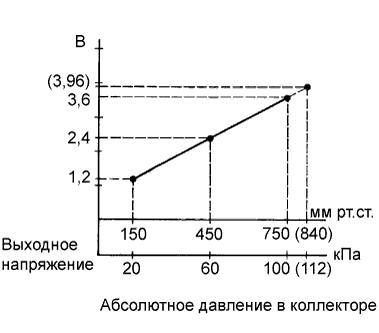
By a built-in sensor unit, the manifold absolute pressure sensor detects the intake manifold pressure as a voltage. The ECM then determines the basic injection duration and basic ignition advance angle based on this voltage.
| DTC No. | DTC Detection Condition | Trouble Area |
|---|---|---|
| P0107 | The output voltage from the vacuum sensor remains 0.5 V or less for 0.5 seconds or more (1-trip detection logic). |
|
| P0108 | The output voltage from the vacuum sensor remains 4.5 V or more for 0.5 seconds or more (1-trip detection logic). |
|
Tech Tips
-
DTC P0107 and P0108 are detected when the ignition switch is ON for approximately 2 seconds.
-
When DTC P0107 or P0108 is detected, check the manifold absolute pressure by entering the following menus: Powertrain / Engine and ECT / Data List / MAP.
| Manifold Absolute Pressure (kPa) | Malfunction |
|---|---|
| Approximately 0 |
|
| 130 or more |
|
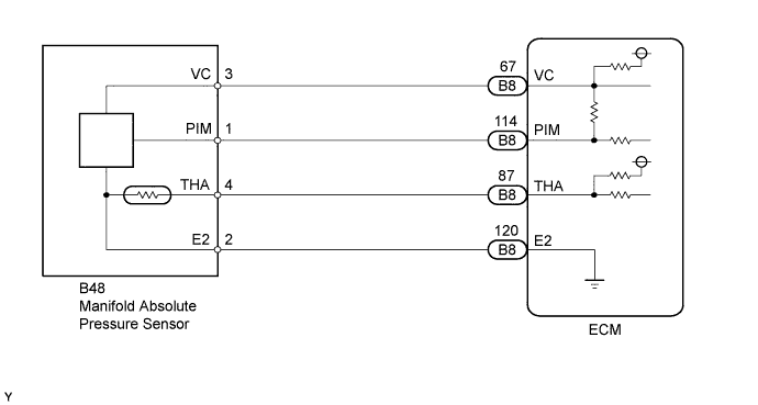
WIRING DIAGRAM
INSPECTION PROCEDURE
Tech Tips
Read freeze frame data using the intelligent tester. The ECM records vehicle and driving condition information as freeze frame data the moment a DTC is stored. When troubleshooting, freeze frame data can help determine if the vehicle was moving or stationary, if the engine was warmed up or not, if the air-fuel ratio was lean or rich, and other data from the time the malfunction occurred.
PROCEDURE
-
READ VALUE USING INTELLIGENT TESTER (MAP)
-
Connect the intelligent tester to the DLC3.
-
Turn the ignition switch to ON.
-
Turn the tester on.
-
Enter the following menus: Powertrain / Engine and ECT / Data List / MAP.
-
Read the MAP value.
Standard Tester Display Switch Condition Specified Condition MAP Ignition switch ON 80 to 110 kPa
NG 
CHECK TERMINAL VOLTAGE (MANIFOLD ABSOLUTE PRESSURE SENSOR) Click here
OK 
CHECK FOR INTERMITTENT PROBLEMS Click here
-
-
CHECK TERMINAL VOLTAGE (MANIFOLD ABSOLUTE PRESSURE SENSOR)
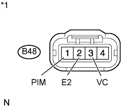
Text in Illustration *1 Front view of wire harness connector:
(to Manifold Absolute Pressure Sensor)
-
Disconnect the manifold absolute pressure sensor connector.
-
Turn the ignition switch to ON.
-
Measure the voltage between the terminals of the manifold absolute pressure sensor connector.
Standard Voltage Tester Connection Switch Condition Specified Condition B48-3 (VC) - B48-2 (E2) Ignition switch ON 4.5 to 5.5 V B48-1 (PIM) - B48-2 (E2) Ignition switch ON 4.0 to 5.0 V -
Reconnect the manifold absolute pressure sensor connector.
NG
CHECK HARNESS AND CONNECTOR (MANIFOLD ABSOLUTE PRESSURE SENSOR - ECM) Click here
OK 
-
-
REPLACE MANIFOLD ABSOLUTE PRESSURE SENSOR
-
Replace the manifold absolute pressure sensor Click here.
NEXT
-
-
CHECK WHETHER DTC OUTPUT RECURS (P0107 OR P0108)
-
Connect the intelligent tester to the DLC3.
-
Turn the ignition switch to ON and turn the tester on.
-
Clear the DTC and turn the ignition switch off.
-
Turn the ignition switch to ON and wait for 2 seconds.
-
Enter the following menus: Powertrain / Engine and ECT / DTC.
-
Read DTCs.
OK No DTC output.
NG 
REPLACE ECM Click here
OK
END
-
-
CHECK HARNESS AND CONNECTOR (MANIFOLD ABSOLUTE PRESSURE SENSOR - ECM)
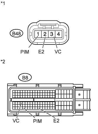
Text in Illustration *1 Front view of wire harness connector:
(to Manifold Absolute Pressure Sensor)
*2 Front view of wire harness connector:
(to ECM)
-
Disconnect the manifold absolute pressure sensor connector.
-
Disconnect the ECM connector.
-
Measure the resistance according to the value(s) in the table below.
Standard Resistance (Check for Open) Tester Connection Condition Specified Condition B48-3 (VC) - B8-67 (VC) Always Below 1 Ω B48-2 (E2) - B8-120 (E2) Always Below 1 Ω B48-1 (PIM) - B8-114 (PIM) Always Below 1 Ω Standard Resistance (Check for Short) Tester Connection Condition Specified Condition B48-3 (VC) or B8-67 (VC) - Body ground Always 10 kΩ or higher B48-2 (E2) or B8-120 (E2) - Body ground Always 10 kΩ or higher B48-1 (PIM) or B8-114 (PIM) - Body ground Always 10 kΩ or higher -
Reconnect the manifold absolute pressure sensor connector.
-
Reconnect the ECM connector.
NG
REPAIR OR REPLACE HARNESS OR CONNECTOR
OK
REPLACE ECM Click here
-