AIR CONDITIONING SYSTEM (for Automatic Air Conditioning System) Air Conditioning Compressor Magnetic Clutch Circuit
DESCRIPTION
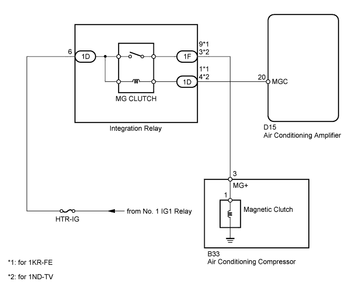
When the air conditioning amplifier is turned on, a magnetic clutch ON signal is sent from the MGC terminal of the air conditioning amplifier. Then, the magnetic clutch relay (MG CLUTCH) turns on to operate the magnetic clutch.
WIRING DIAGRAM
INSPECTION PROCEDURE
Note
Inspect the fuses for circuits related to this system before performing the following inspection.
PROCEDURE
-
CHECK CAN COMMUNICATION SYSTEM
-
Connect the intelligent tester to the DLC3.
-
Turn the ignition switch to ON.
-
Turn the intelligent tester on.
-
Select "Communication Bus Check"
OK All ECUs and sensors connected to the CAN communication system are displayed.
NG 
GO TO CAN COMMUNICATION SYSTEM Click here
OK 
-
-
PERFORM ACTIVE TEST USING INTELLIGENT TESTER (MAGNETIC CLUTCH RELAY)
-
Connect the intelligent tester to the DLC3.
-
Turn the ignition switch to ON.
-
Turn the intelligent tester on.
-
Enter the following menus: Body / Air Conditioner / Active Test.
-
According to the display on the intelligent tester, read the Data List.
Air Conditioner Tester Display Test Part Control Range Diagnostic Note Magnetic Clutch Relay Magnetic clutch relay
ON or OFF
OFF, ON - OK The magnetic clutch operates normally.
NG 
INSPECT INTEGRATION NO.1 RELAY (MAGNETIC CLUTCH RELAY) Click here
OK
-
-
READ VALUE USING INTELLIGENT TESTER (A/C SIGNAL)
-
Connect the intelligent tester to the DLC3.
-
Turn the ignition switch to ON.
-
Turn the intelligent tester on.
-
Enter the following menus: Powertrain / Engine / Data List.
-
According to the display on the intelligent tester, read the Data List.
Engine Tester Display Measurement Item/Range Normal Condition Diagnostic Note A/C Signal A/C switch signal /
ON or OFF
ON: A/C on
OFF: A/C off
- OK The display is as specified in the normal condition.
NG
REPLACE AIR CONDITIONING AMPLIFIER Click here
OK 
PROCEED TO NEXT SUSPECTED AREA SHOWN IN PROBLEM SYMPTOMS TABLE Click here
-
-
INSPECT INTEGRATION NO.1 RELAY (MAGNETIC CLUTCH RELAY)
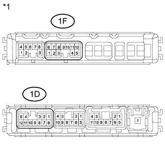
Text in Illustration *1 Component without harness connected
(Integration Relay)
-
Remove the integration relay from the engine room relay block.
-
Measure the resistance according to the value(s) in the table below.
Standard Resistance Tester Connection Condition Specified Condition 1D-6 - 1F-9*1
1D-6 - 1F-3*2
When battery voltage is not applied between terminals 10 kΩ or higher When battery voltage is applied to terminals 1D-6 and 1D-1*1, 1D-4*2 Below 1 Ω
-
*1: for 1KR-FE
-
*2: for 1ND-TV
-
-
Reinstall the integration relay.
NG
REPLACE INTEGRATION NO.1 RELAY (MAGNETIC CLUTCH RELAY)
OK
-
-
CHECK HARNESS AND CONNECTOR (AIR CONDITIONING AMPLIFIER - BATTERY)
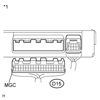
Text in Illustration *1 Rear view of wire harness connector
(to Air Conditioning Amplifier)
-
Disconnect the D15 air conditioning amplifier connector.
-
Measure the voltage according to the value(s) in the table below.
Standard Voltage Tester Connection Switch Condition Specified Condition D15-20 (MGC) - Body ground Ignition switch off Below 1 V Ignition switch ON 11 to 14 V -
Reconnect the air conditioning amplifier connector.
NG
CHECK HARNESS AND CONNECTOR (INTEGRATION RELAY - BATTERY) Click here
OK
-
-
INSPECT AIR CONDITIONING AMPLIFIER (MGC VOLTAGE)
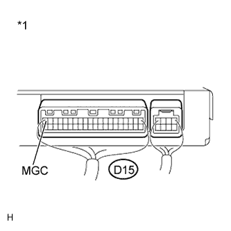
Text in Illustration *1 Component with harness connected
(Air Conditioning Amplifier)
-
Remove the air conditioning amplifier with its connectors still connected Click here.
-
Measure the voltage according to the value(s) in the table below.
Standard Voltage Tester Connection Switch Condition Specified Condition D15-20 (MGC) - Body ground Engine running and A/C switch on Below 1 V Engine running and A/C switch off 11 to 14 V -
Reinstall the air conditioning amplifier.
NG
REPLACE AIR CONDITIONING AMPLIFIER Click here
OK
-
-
INSPECT AIR CONDITIONING COMPRESSOR (COMPRESSOR HARNESS)
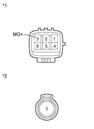
Text in Illustration *1 Component without harness connected
(Air Conditioning Compressor)
*2 Component without harness connected
(Magnetic Clutch)
-
Disconnect the D39 air conditioning compressor connector.
-
Disconnect the magnetic clutch connector.
-
Measure the resistance according to the value(s) in the table below.
Standard Resistance Tester Connection Condition Specified Condition 3 (MG+) - 1 Always Below 1 Ω 3 (MG+) - Body ground Always 10 kΩ or higher Result Result Proceed to OK A NG (for 1KR-FE) B NG (for 1ND-TV) C
B
REPLACE AIR CONDITIONING COMPRESSOR Click here
C
REPLACE AIR CONDITIONING COMPRESSOR Click here
A
-
-
INSPECT MAGNETIC CLUTCH
-
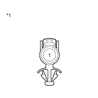
Text in Illustration *1 Component without harness connected
(Magnetic Clutch)
Measure the resistance according to the value(s) in the table below.
Standard Resistance Tester Connection Condition Specified Condition 1 - Body ground Always 3.4 to 3.8 Ω -
When connector terminal 1 is connected to the positive (+) battery terminal, check that the following occurs: 1) the magnetic clutch operating sound can be heard, and 2) the magnetic clutch hub and rotor lock.
Result Result Proceed to OK A NG (for 1KR-FE) B NG (for 1ND-TV) C -
Reconnect the air conditioning compressor connector.
-
Reconnect the magnetic clutch connector.
B
REPLACE MAGNETIC CLUTCH Click here
C
REPLACE MAGNETIC CLUTCH Click here
A
-
-
CHECK HARNESS AND CONNECTOR (AIR CONDITIONING COMPRESSOR - INTEGRATION RELAY)
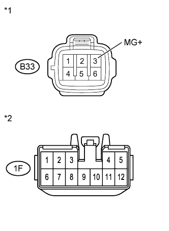
Text in Illustration *1 Front view of wire harness connector
(to Air Conditioning Compressor)
*2 Front view of wire harness connector
(to Integration Relay)
-
Disconnect the B33 air conditioning compressor connector.
-
Remove the 1F integration relay connector.
-
Measure the resistance according to the value(s) in the table below.
Standard Resistance Tester Connection Condition Specified Condition B33-3 (MG+) - 1F-9*1
B33-3 (MG+) - 1F-3*2
Always Below 1 Ω B33-3 (MG+) - Body ground Always 10 kΩ or higher
-
*1: for 1KR-FE
-
*2: for 1ND-TV
-
-
Reconnect the integration relay connector.
-
Reconnect the air conditioning compressor connector.
NG
REPAIR OR REPLACE HARNESS OR CONNECTOR
OK
REPLACE AIR CONDITIONING AMPLIFIER Click here
-
-
CHECK HARNESS AND CONNECTOR (INTEGRATION RELAY - BATTERY)
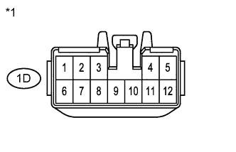
Text in Illustration *1 Front view of wire harness connector
(to Integration Relay)
-
Remove the 1D integration relay connector.
-
Measure the voltage according to the value(s) in the table below.
Standard Voltage Tester Connection Switch Condition Specified Condition 1D-6 - Body ground Ignition switch off Below 1 V 1D-6 - Body ground Ignition switch ON 11 to 14 V -
Reconnect the integration relay connector.
NG
REPAIR OR REPLACE HARNESS OR CONNECTOR
OK
REPAIR OR REPLACE HARNESS OR CONNECTOR (AIR CONDITIONING AMPLIFIER - INTEGRATION RELAY)
-
-
REPLACE AIR CONDITIONING AMPLIFIER
-
Replace the air conditioning amplifier with a normal one Click here.
-
Check that the condition returns to normal.
OK Same problem does not occur. Result Result Proceed to OK A NG (for 1KR-FE) B NG (for 1ND-TV) C
B
REPLACE ECM Click here
C
REPLACE ECM Click here
A
END (AIR CONDITIONING AMPLIFIER IS FAULTY)
-