ENGINE IMMOBILISER SYSTEM (w/o Entry and Start System), Diagnostic DTC:B2799

| DTC Code | DTC Name |
|---|---|
| B2799 | Engine Immobiliser System Malfunction |
DESCRIPTION
This DTC is stored when one of the following occurs: 1) the ECM detected errors in its own communications with the transponder key ECU; 2) the ECM detects errors in the communication lines; or 3) the ECU communication ID between the transponder key ECU and ECM is different and an engine start is attempted. Before troubleshooting for this DTC, make sure that no transponder key ECU DTCs are present. If present, troubleshoot the transponder key ECU DTCs first.
| DTC No. | DTC Detection Condition | Trouble Area |
|---|---|---|
| B2799 |
|
|
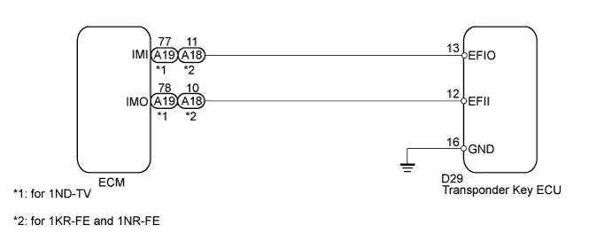
WIRING DIAGRAM
INSPECTION PROCEDURE
Note
-
If the transponder key ECU is replaced, register key and ECU - ECM communication ID.
-
When the ECM is replaced, reregister the ECU - ECM communication ID.
PROCEDURE
-
RE-REGISTER ECU COMMUNICATION ID
-
Re-register the ECU communication ID between the transponder key ECU and ECM.
NEXT 
-
-
CLEAR DTC
-
Clear the DTC Click here.
NEXT
-
-
CHECK FOR DTC
-
Check for DTCs Click here.
OK DTC is not output.
NG 
CHECK CONNECTION OF CONNECTOR Click here
OK 
END (ECU COMMUNICATION ID IS DEFECTIVE)
-
-
CHECK CONNECTION OF CONNECTOR
-
Turn the ignition switch off.
-
Check that the connectors are properly connected to the ECM and the transponder key ECU.
OK Connectors are properly connected.
NG 
CONNECT CONNECTORS PROPERLY
OK
-
-
CHECK HARNESS AND CONNECTOR (TRANSPONDER KEY ECU - ECM)
-
Disconnect the D29 transponder key ECU and A18 or A19 ECM connectors.
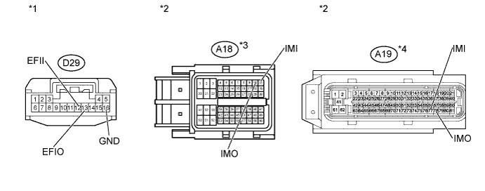
Text in Illustration *1 Front view of wire harness connector
(to Transponder key ECU)
*2 Front view of wire harness connector
(to ECM)
*3 for 1KR-FE and 1NR-FE *4 for 1ND-TV -
Measure the resistance according to the value(s) in the table below.
-
for 1ND-TV
Standard Resistance Tester Connection Condition Specified Condition D29-12 (EFII) - A19-78 (IMO) Always Below 1 Ω D29-13 (EFIO) - A19-77 (IMI) Always Below 1 Ω D29-12 (EFII) - Body ground Always 10 kΩ or higher D29-13 (EFIO) - Body ground Always 10 kΩ or higher -
for 1KR-FE and 1NR-FE
Standard Resistance Tester Connection Condition Specified Condition D29-12 (EFII) - A18-10 (IMO) Always Below 1 Ω D29-13 (EFIO) - A18-11 (IMI) Always Below 1 Ω D29-12 (EFII) - Body ground Always 10 kΩ or higher D29-13 (EFIO) - Body ground Always 10 kΩ or higher
-
-
Reconnect the ECU and ECM connectors.
NG
REPAIR OR REPLACE HARNESS OR CONNECTOR
OK
-
-
REPLACE ECM
-
Replace the ECM.
-
for 1ND-TV Click here.
-
for 1KR-FE Click here.
-
for 1NR-FE Click here.
-
NEXT
-
-
ECU CODE REGISTRATION
-
Re-register the ECU communication ID between the transponder key ECU and ECM.
NEXT
-
-
CLEAR DTC
-
Clear the DTC Click here.
NEXT
-
-
CHECK FOR DTC
-
Check for DTCs Click here.
OK DTC is not output.
NG
REPLACE TRANSPONDER KEY ECU
OK
END (ECM IS DEFECTIVE)
-